Domestic fans
 Industrial fans
 Single-room air handling units with heat recovery
 Air handling units
  Smoke extraction and ventilation
 Ventilation accessories
 Ventilation ducts and fittings
 Air distribution
 Measurement and control technology
 Ventilation sets and vents
Blauberg KOMFORT LW 2100-4

 EAN4058448021930
 - Description
- Characteristics
- Capacity diagram
- Downloads
- Designation key
- Accessories
- Dimensions
- Additional diagrams
- Hot water coil calculation diagram
| FEATURES
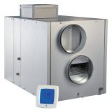
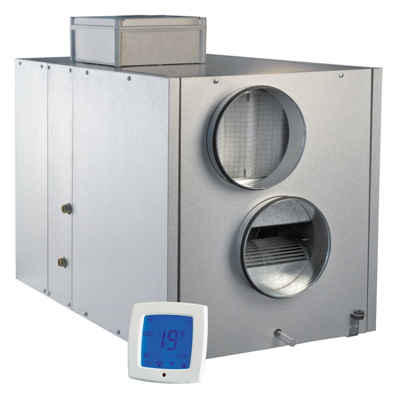
Air handling units for efficient supply and exhaust ventilation in flats, houses, cottages and other buildings. Heat recovery minimises ventilation heat losses. Control of air exchange for creating comfortable indoor microclimate. Compatible with round Ø 250 to 315 mm air ducts. DESIGNThe casing is made of double-skinned aluzinc panels, internally filled with 50 mm mineral wool layer for heat and sound insulation. The casing has fixing brackets with vibration absorbing connectors for easy installation. The spigots for connection to the air ducts are located at the side of the unit and are rubber sealed for airtight connection to the air ducts. The hinged casing side panels ensure easy access to the internals for cleaning, filter replacement and other maintenance operations. |
FANS
Asynchronous external rotor motors and centrifugal double-intake impellers with forward curved blades are used for air supply and exhaust. Integrated motor overheating protection with automatic restart. Dynamically balanced impellers. Equipped with ball bearings for longer service life. Reliable and quiet operation. AIR FILTRATIONThe built-in G4 supply filter and G4 extract filter provide air filtration. |
|
|
|
||
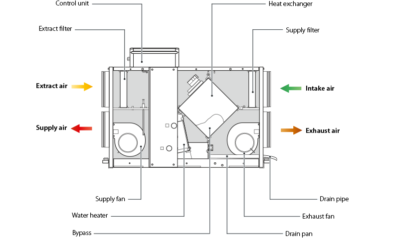
| HEAT RECOVERY
The electronic protection system based on bypass and heater is used for freezing protection of the unit in cold seasons. The bypass damper is opened and the heater is turned on automatically according to temperature sensor readings. Cold intake air passes by the heat exchanger and is warmed up to set temperature in the heat exchanger. Synchronously extract air that passes by the heat exchanger is used for its defrosting. After a freezing danger is over the bypass damper is closed, the heater is turned off. The heat exchanger reverts to the normal operation mode. MOUNTINGMounting to floor, ceiling or wall with fixing brackets. The correct mounted unit must provide condensate collecting and drainage and free access to the hinged side panel for servicing and filter replacement. |
CONTROL AND AUTOMATION
The unit incorporates an integrated control system with a wall-mounted control panel and LCD display. The standard delivery set includes a 10 m cable for connection of the unit and the control panel. Control panel functions:
The unit is equipped with a water (glycol) heater for operation at low outside air temperature. The integrated water heater is activated to warm up supply air flow if set indoor air temperature may not be reached by means of heat recovery only. Heat medium temperature control ensures supply air temperature maintaining. The air temperature sensor downstream of the waterheating coils and the return water temperature sensor are used for freezing protection of the water heater. |
|

| Parameter | KOMFORT LW 2100-4 | Measurement unit |
|---|---|---|
| Voltage | 230 | V |
| Phase | 1 | ˜ |
| Frequency | 50 | Hz |
| Power | 1300 | W |
| Current | 5.68 | A |
| RPM | 1150 | min-1 |
| Maximum air flow | 583 | l/s |
| Maximum air flow | 2100 | m³/h |
| Number of water coil rows | 4 | - |
| Sound pressure level at 3 m | 65 | dBА |
| Insulation | 50 mm mineral wool | mm |
| Transported air temperature | -25...+40 | °С |
| Heat recovery efficiency | 77 | % |
| Heat exchanger type | cross-flow | - |
| Heat exchanger material | polystyrene | - |
| Weight | 99 | kg |
| Connected air duct diameter | 315 | mm |
| Casing material | aluzinc | - |
| Mounting | ceiling mounting, wall mounting, floor mounting | - |
- Selection method:
- Air capacity:
- Pressure:
- Air capacity: --
- Pressure: ---
| Series | Spigot modification | Heater type | Rated air flow [m³/h] | Number of water heater rows | |
| KOMFORT | L: horizontal spigot orientation | W: water heater | 800; 1100; 1700; 2100 | – | 4 |


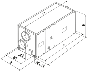
| Model | Overall dimensions [mm] | ||||||
| ØD | B | B1 | H | L | L1 | L2 | |
| KOMFORT LW 2100-4 | 314 | 842 | 581 | 814 | 1345 | 1388 | 1445 |


| How to use water heater diagrams.The air flow is 2000 m³/h and the air speed in the heater is 3.75 m/s ①. | ||
| To calculate the maximum air temperature find the intersection point of the air flow line ① with the rated outer temperature shown in blue line (e.g., -15 °С) and draw the line ② to the left until it crosses the water in/out temperature curve (e.g., +70/+50). From this point draw a vertical line to the supply air temperature downstream of the heater (+31 °С) ③. | To calculate the heater power find the intersection point of the air flow ① with the rated winter temperature shown in red line (e.g., -15 °С) and draw the line ④ to the right until it crosses the water in/out temperature curve (e.g., +70/+50). From this point draw a vertical line to the heater power axis (35.0 kW) ⑤. | To calculate the required water flow in the heater prolong this line ⑥ downwards to the water flow axis (0.43 l/s). To calculate the water pressure drop in the heater find the intersection point of the line ⑥ with the pressure loss curve and prolong the line ⑦ to the right on the water pressure drop axis (9.0 kPa). |