Blauberg Axis-FP 60 Hz


- Description
- Modifications
- Downloads
- Designation key
- Accessories
- Operation of fans with frequency converters
USE
The fans are used for extraction of smoke in case of fire and removal of hot air outside. The fans are also used for general ventilation systems.The fans are rated for permanent operation at ambient air temperatures from -60 °C up to +50 °C (depends on climatic category, see the Designation key). The fans are able to operate 2 hours at the temperatures +300 °C and +400 °C.The fans with a fire resistance class of 200 °C/2 hours can be produced on request. The characteristics of the 200 °C/2 hours fans are completely identical to 300 °C/2 hours fans. DESIGNThe fan consists of a casing, an impeller and a motor. The metal casing with rolled flanges helps achieve outstanding rigidity and minimum clearances between the casing and the blades. There is an inspection hatch in the casing for easy maintenance. All the casing components are powder coated for improved protection against the environmental effects. The weight of the fans may differ from the one stated in the catalogue and depends on the components used (motor, terminal box, etc.). MOTORThe fans are equipped with three-phase (400 V/60 Hz) motors. Motor ingress protection rating is IP55.The motor RPM could be changed insignificantly in accordance with the actual motor datasheet. Consequently, the airflow could be altered respectively as well. Depending on the model, the fans have single- or double-speed modifications.The single-speed models are equipped with 2-, 4- or 6-pole motors.The double-speed models are equipped with 2/4-, 4/6- or 4/8-pole motors. |
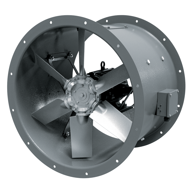
Depending on the size and the required air capacity the fans are equipped with impellers with 4, 5, 6, 7, 8, 9 or 12 blades angled from 20° to 50° to ensure precise matching of fans with the operating point. The specially designed impeller blades ensure high efficiency of the fan while keeping noise well under control. The impellers are dynamically balanced. Low weight and low moment of the impeller inertia help reduce the fan start-up time. The fan blades are made of cast aluminium. MOUNTINGThe fans can be mounted on any flat surface or directly into a ventilation duct. The units are suitable for both horizontal and vertical configurations. Installation in the air duct requires flanges to attach the fan to the ductwork. To attach the fan to the floor, the wall or the ceiling use the O-AF carriers (not included as standard, should be purchased separately). The fans are suitable for installation on rooftops. |
|
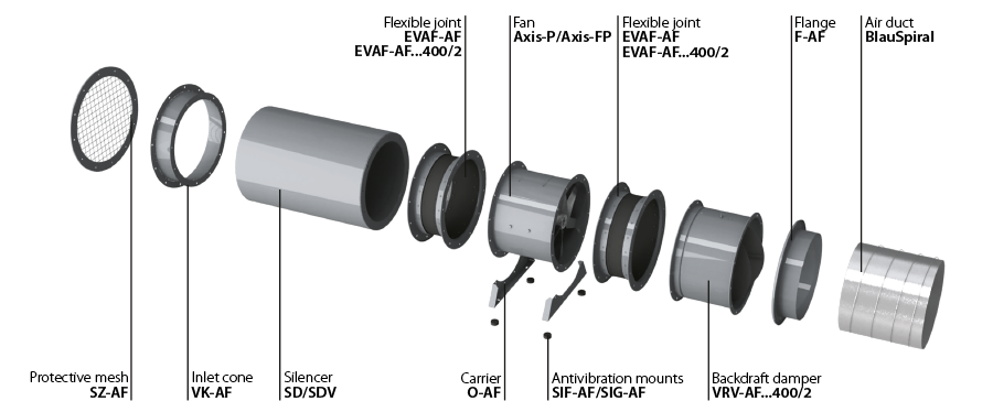
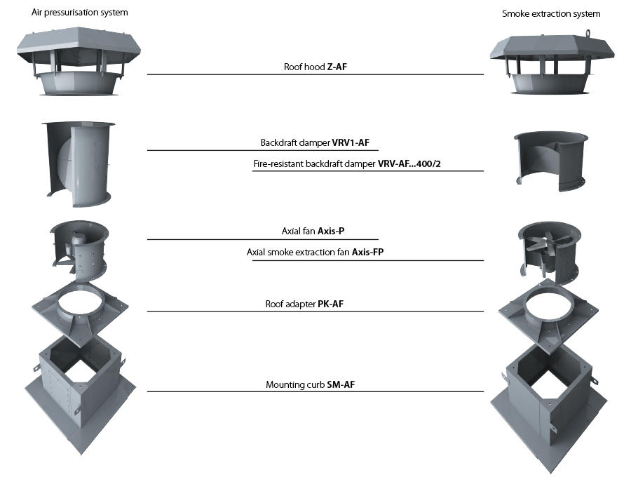
COMPLETE SOLUTIONS FOR AXIAL FANS | ||
![]() |
||
INSTALLATION EXAMPLE OF AXIAL FANS ON ROOFTOP | ||
![]() |
||
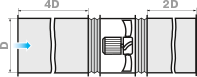
FAN INSTALLATION INTO AN AIR DUCT SYSTEM
To ensure a uniform air flow, the fan should be preceded by a straight duct section with a cross-section area equal to half of that of the fan. The length of the duct section should be 3 ÷ 4 D (D is the inner diameter of the fan). The length of the straight duct section downstream of the fan should be 1.5 ÷ 2 D.Reduction of the recommended duct length values results in a drop of the fan pressure and performance. To reduce noise and vibration, use the EVAF-AF flexible joints. 
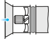
Axial fans without upstream ducting must be equipped with a VK-AF inlet cone to improve the air flow parameters. 
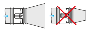
If the axial fan is a terminal device of the ventilation system (i.e. there is no downstream ducting), the unit must be equipped with a diffuser to reduce the air flow velocity and the fan dynamic pressure. Reduction of the air discharge velocity results in a significant reduction of shock losses which are proportional to the square of velocity decrement.The fan should not be equipped with a downstream contractor. |
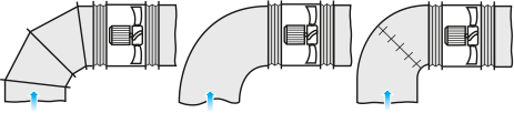
INSTALLATION NEAR BENDS
To install the fan directly downstream of a bend (elbow), use a curved section with a large bending radius or an array of internal guide vanes. 
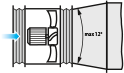
When changing from a smaller diameter to a larger one use a connector diffuser with the maximum opening angle of 12°. 
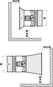
To ensure normal operation of the fan in an obstructed space, make sure to provide for a sufficient distance between the inlet and outlet flanges and the floor, walls, bulky equipment and obstacles. |
Modification name | |
---|---|
Axis-FP 1000-4/6D/10/3.3-5/29/AL | |
Axis-FP 1000-4/8D/11/3-5/30/AL | |
Axis-FP 1000-4D/11-5/30/AL | |
Axis-FP 1000-6D/1.5-5/20/AL | |
Axis-FP 1120-4/6D/10/3.3-5/25/AL | |
Axis-FP 1120-4/8D/11/3-5/26/AL | |
Axis-FP 1120-4D/11-5/26/AL | |
Axis-FP 1120-6D/2.2-5/20/AL | |
Axis-FP 1250-4/6D/16/6.5-4/22/AL | |
Axis-FP 1250-4/8D/17/4.3-4/23/AL | |
Axis-FP 1250-4D/18.5-4/23/AL | |
Axis-FP 1250-6D/11-4/38/AL | |
Axis-FP 400-2/4D/1.1/0.25-3/30/AL | |
Axis-FP 400-2/4D/1.1/0.25-4/20/AL | |
Axis-FP 400-2D/0.55-3/25/AL | |
Axis-FP 400-2D/0.75-4/20/AL | |
Axis-FP 400-4D/0.37-3/30/AL | |
Axis-FP 400-4D/0.37-4/25/AL | |
Axis-FP 450-2/4D/1.1/0.25-3/25/AL | |
Axis-FP 450-2/4D/1.5/0.37-4/20/AL | |
Axis-FP 450-2D/0.75-3/25/AL | |
Axis-FP 450-2D/1.5-4/20/AL | |
Axis-FP 450-4D/0.37-3/25/AL | |
Axis-FP 450-4D/0.37-4/20/AL | |
Axis-FP 500-2/4D/1.1/0.25-3/21.5/AL | |
Axis-FP 500-2/4D/2.5/0.65-4/20/AL | |
Axis-FP 500-2D/1.1-3/21.5/AL | |
Axis-FP 500-2D/2.2-4/20/AL | |
Axis-FP 500-4D/0.37-3/25/AL | |
Axis-FP 500-4D/0.37-4/20/AL | |
Axis-FP 560-2/4D/2.5/0.65-5/25/AL | |
Axis-FP 560-2/4D/3.1/0.8-4/20/AL | |
Axis-FP 560-2D/2.2-5/25/AL | |
Axis-FP 560-2D/3-4/20/AL | |
Axis-FP 560-4D/0.37-3/25/AL | |
Axis-FP 560-4D/0.37-4/20/AL | |
Axis-FP 630-2/4D/12/3-6/30/AL | |
Axis-FP 630-2/4D/12/3-7/38.5/AL | |
Axis-FP 630-2/4D/2.5/0.65-5/25/AL | |
Axis-FP 630-2D/11-6/30/AL | |
Axis-FP 630-2D/11-7/38.5/AL | |
Axis-FP 630-2D/2.2-5/25/AL | |
Axis-FP 630-4/6D/0.55/0.2-4/25/AL | |
Axis-FP 630-4/6D/1.1/0.3-6/20/AL | |
Axis-FP 630-4/8D/0.6/0.15-4/25/AL | |
Axis-FP 630-4/8D/0.8/0.2-6/20/AL | |
Axis-FP 630-4D/0.37-4/25/AL | |
Axis-FP 630-4D/0.75-6/20/AL | |
Axis-FP 710-4/6D/1.1/0.3-4/16.5/AL | |
Axis-FP 710-4/6D/1.1/0.3-6/20/AL | |
Axis-FP 710-4/8D/0.8/0.2-4/16.5/AL | |
Axis-FP 710-4/8D/0.8/0.2-6/20/AL | |
Axis-FP 710-4D/0.75-4/16.5/AL | |
Axis-FP 710-4D/0.75-6/20/AL | |
Axis-FP 710-6D/0.25-4/16.5/AL | |
Axis-FP 710-6D/0.25-6/20/AL | |
Axis-FP 800-4/6D/1.1/0.3-4/16.5/AL | |
Axis-FP 800-4/6D/1.1/0.3-6/20/AL | |
Axis-FP 800-4/8D/1.2/0.3-4/16.5/AL | |
Axis-FP 800-4/8D/1.2/0.3-6/20/AL | |
Axis-FP 800-4D/1.1-4/16.5/AL | |
Axis-FP 800-4D/1.1-6/20/AL | |
Axis-FP 800-6D/0.37-4/16.5/AL | |
Axis-FP 800-6D/0.37-6/20/AL | |
Axis-FP 900-4/6D/10/3.3-3/41/AL | |
Axis-FP 900-4/8D/11/3-3/43/AL | |
Axis-FP 900-4D/11-3/43/AL | |
Axis-FP 900-6D/0.75-3/20/AL | |
Axis-FP 900-6D/0.75-3/20/AL |
|
|
|
|
|
|
|
|
|
|
|
|
|
|
|
|
|
|
|
|
|
|
|
|
|
|
|
|
|
|
|
|
|
|
|
|
|
|
|
|
|
|
|
|
|
|
|
|
|
|
|
|
|
|
|
|
|
|
|
|
|
|
|
|
|
|
|
|
|
|
|
|
|
|
|
|
|
|
|
|
|
|
|
|
Fan | ![]() |
Ø 400 | Ø 450 | Ø 500 | Ø 560 | Ø 630 | Ø 710 | Ø 800 | Ø 900 | Ø 1000 | Ø 1120 | Ø 1250 |
Carrier | ![]() |
O-AF-400 | O-AF-450 | O-AF-500 | O-AF-560 | O-AF-630 | O-AF-710 | O-AF-800 | O-AF-900 | O-AF-1000 | O-AF-1120 | O-AF-1250 |
Flange | ![]() |
F-AF-400 | F-AF-450 | F-AF-500 | F-AF-560 | F-AF-630 | F-AF-710 | F-AF-800 | F-AF-900 | F-AF-1000 | F-AF-1120 | F-AF-1250 |
Flexible joint | ![]() |
EVAF-AF-400 | EVAF-AF-450 | EVAF-AF-500 | EVAF-AF-560 | EVAF-AF-630 | EVAF-AF-710 | EVAF-AF-800 | EVAF-AF-900 | EVAF-AF-1000 | EVAF-AF-1120 | EVAF-AF-1250 |
Fire-resistant flexible joint (up to 400 °C) | ![]() |
EVAF-AF-400-400/2 | EVAF-AF-450-400/2 | EVAF-AF-500-400/2 | EVAF-AF-560-400/2 | EVAF-AF-630-400/2 | EVAF-AF-710-400/2 | EVAF-AF-800-400/2 | EVAF-AF-900-400/2 | EVAF-AF-1000-400/2 | EVAF-AF-1120-400/2 | EVAF-AF-1250-400/2 |
Hood | ![]() |
Z-AF-400 | Z-AF-450 | Z-AF-500 | Z-AF-560 | Z-AF-630 | Z-AF-710 | Z-AF-800 | Z-AF-900 | Z-AF-1000 | Z-AF-1120 | Z-AF-1250 |
Roof adapter | ![]() |
PK-AF-400 | PK-AF-450 | PK-AF-500 | PK-AF-560 | PK-AF-630 | PK-AF-710 | PK-AF-800 | PK-AF-900 | PK-AF-1000 | PK-AF-1120 | PK-AF-1250 |
Mounting curb | ![]() |
SM-AF-400-450 | SM-AF-400-450 | SM-AF-500 | SM-AF-560-630 | SM-AF-560-630 | SM-AF-710-800 | SM-AF-710-800 | SM-AF-900 | SM-AF-1000-1120 | SM-AF-1000-1120 | SM-AF-1250 |
Inlet cone | ![]() |
VK-AF-400 | VK-AF-450 | VK-AF-500 | VK-AF-560 | VK-AF-630 | VK-AF-710 | VK-AF-800 | VK-AF-900 | VK-AF-1000 | VK-AF-1120 | VK-AF-1250 |
Backdraft damper | ![]() |
VRV-AF-400 | VRV-AF-450 | VRV-AF-500 | VRV-AF-560 | VRV-AF-630 | VRV-AF-710 | VRV-AF-800 | VRV-AF-900 | VRV-AF-1000 | VRV-AF-1120 | VRV-AF-1250 |
Fire-resistant backdraft damper (up to 400 °C) | ![]() |
VRV-AF-400-400/2 | VRV-AF-450-400/2 | VRV-AF-500-400/2 | VRV-AF-560-400/2 | VRV-AF-630-400/2 | VRV-AF-710-400/2 | VRV-AF-800-400/2 | VRV-AF-900-400/2 | VRV-AF-1000-400/2 | VRV-AF-1120-400/2 | VRV-AF-1250-400/2 |
Backdraft damper | ![]() |
VRV1-AF-400 | VRV1-AF-450 | VRV1-AF-500 | VRV1-AF-560 | VRV1-AF-630 | VRV1-AF-710 | VRV1-AF-800 | VRV1-AF-900 | VRV1-AF-1000 | VRV1-AF-1120 | VRV1-AF-1250 |
Silencer SD | ![]() |
SD-400-1D | SD-450-1D | SD-500-1D | SD-560-1D | SD-630-1D | SD-710-1D | SD-800-1D | SD-900-1D | SD-1000-1D | SD-1120-1D | SD-1250-1D |
SD-400-1.5D | SD-450-1.5D | SD-500-1.5D | SD-560-1.5D | SD-630-1.5D | SD-710-1.5D | SD-800-1.5D | SD-900-1.5D | SD-1000-1.5D | SD-1120-1.5D | SD-1250-1.5D | ||
SD-400-2D | SD-450-2D | SD-500-2D | SD-560-2D | SD-630-2D | SD-710-2D | SD-800-2D | SD-900-2D | SD-1000-2D | SD-1120-2D | SD-1250-2D | ||
Silencer SDV | ![]() |
SDV-400-1D | SDV-450-1D | SDV-500-1D | SDV-560-1D | SDV-630-1D | SDV-710-1D | SDV-800-1D | SDV-900-1D | SDV-1000-1D | SDV-1120-1D | SDV-1250-1D |
SDV-400-1.5D | SDV-450-1.5D | SDV-500-1.5D | SDV-560-1.5D | SDV-630-1.5D | SDV-710-1.5D | SDV-800-1.5D | SDV-900-1.5D | SDV-1000-1.5D | SDV-1120-1.5D | SDV-1250-1.5D | ||
SDV-400-2D | SDV-450-2D | SDV-500-2D | SDV-560-2D | SDV-630-2D | SDV-710-2D | SDV-800-2D | SDV-900-2D | SDV-1000-2D | SDV-1120-2D | SDV-1250-2D | ||
Protective mesh | ![]() |
SZ-AF-400 | SZ-AF-450 | SZ-AF-500 | SZ-AF-560 | SZ-AF-630 | SZ-AF-710 | SZ-AF-800 | SZ-AF-900 | SZ-AF-1000 | SZ-AF-1120 | SZ-AF-1250 |
Antivibration mount | ![]() |
SIF-AF* | SIF-AF* | SIF-AF* | SIF-AF* | SIF-AF* | SIF-AF* | SIF-AF* | SIF-AF* | SIF-AF* | SIF-AF* | SIF-AF* |
Antivibration mount | ![]() |
SIG-AF* | SIG-AF* | SIG-AF* | SIG-AF* | SIG-AF* | SIG-AF* | SIG-AF* | SIG-AF* | SIG-AF* | SIG-AF* | SIG-AF* |
* selection according to the fan weight
Ventilation systems produce a heavy load on the electrical systems of a building. DIRECT ON-LINE STARTING (DOL)As a rule, smoke extraction systems utilize large high-performance fans.During starting the high inertia of the shaft causes a substantial increase in the start-up time – i.e. the time from the application of power to reaching the rated speed.As a result the motor is subjected to high starting current for a prolonged period of time.
Standard switchgear (automatic circuit breakers, contactors and motor starters) is not designed to withstand prolonged overloads causing the fan to shut down automatically during starting. Using switchgear with a higher maximum current rating renders the electric motor protection system less sensitive.As a result the switchgear will not be able to detect motor overload in time due to a higher current sensing threshold.Such challenges can only be addressed by utilizing a soft starter or a frequency converter to start the fan without causing a prolonged overload.
APPLICATIONS IN VENTILATION SYSTEMS Using an FC or a soft starter allows to reduce the starting current thereby avoiding a loss of voltage in the electrical mains. In addition to that the starting torque and mechanical strain on equipment are also reduced which translates into extended maintenance and repair intervals. General exhaust ventilation (GV) systems and emergency smoke extraction (SE) systems of car parks, warehouses, utility and industrial spaces can be integrated into a single system at the design level. As the air flow rate a GV system is considerably lower than that in an SE system a high-capacity fan rated for smoke extraction duty runs in partial load mode. Frequency converters can be programmed for several fixed-speed settings to enable operation in GV and SE modes. The fan operating modes can be switched upon receiving an external signal from the control system. Such integration of ventilation systems allows overall cost savings. FC-51 AND FC-101: WHEN TO USE?This catalogue features two series of frequency converters: FC-51 and FC-101. The FC-51 series is only suitable for general ventilation systems. If intended for a smoke extraction system, the fans should be fitted with the FC-101 series units as they feature an integrated fire mode. When activated the integrated protection equipment of the frequency converter is overridden enabling the unit to continue operation despite the possibility of sustaining irreparable damage due to overheating or overloading. In case of a fire, the FC-101 series frequency converters are capable of maintaining a higher air pressure level at landings compared to other areas of the building in order to keep the landings smoke-free. |
Therefore, reducing the power consumption is among the top priorities for construction project designers. FREQUENCY CONVERTERA frequency converter (FC) consists of two main component blocks. One converts alternating current (50 or 60 Hz) into direct current. The other converts direct current into alternating current of variable frequency ranging from 0 to 250 Hz. By controlling the frequency output the FC offers a broad range of motor speed regulation.
During the starting the FC raises the frequency from 0 Hz to the electrical mains frequency (50 or 60 Hz). As the frequency is increased gradually, the motor can be assumed to operate at its nominal speed for a given frequency value. Furthermore, on the assumption that the motor runs at its nominal speed the nominal torque should be immediately available whereas the current will be approximately equal to the nominal value.
SOFT STARTER Unlike an FC, a soft starter does not change the frequency of speed. Instead it gradually increases the voltage supplied to the motor – from the initial level to the nominal level.The very low voltage initially supplied to the motor during starting helps avoid sudden jolts. Both voltage and torque increase gradually.
|
||||||||||||||
![]() |
![]() |
||||||||||||||
FREQUENCY CONVERTERS MICRO DRIVE FC-51 | FREQUENCY CONVERTERS BASIC DRIVE FC-101 | ||||||||||||||
More | More |