Blauberg Axis-P
- Description
- Downloads
- BIM
| USE
The fans are used:
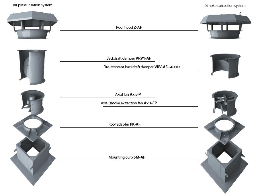
The metal casing with rolled flanges helps achieve outstanding rigidity and minimum clearances between the casing and the blades. There is an inspection hatch in the casing for easy maintenance. All the casing components are powder coated for improved protection against the environmental effects. The weight of the fans may differ from the one stated in the catalogue and depends on the components used (motor, terminal box, etc.). MOUNTINGThe fans can be mounted on any flat surface or directly into a ventilation duct. The units are suitable for both horizontal and vertical configurations. In-duct installation requires flanges to attach the fan to the ductwork. To attach the fan to the floor, the wall or the ceiling use the O-AF carriers (not included as standard, should be purchased separately). The units are suitable for installation on rooftops to provide direct supply of outdoor air to the stairway areas. |
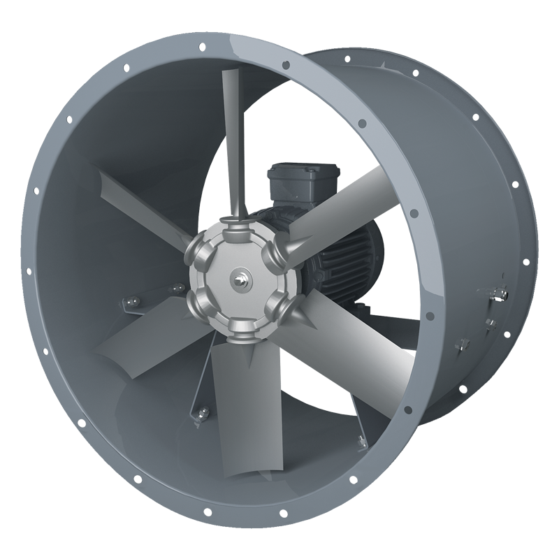
The fans are equipped with three-phase (400 V/50 Hz) single-speed 2-, 4- or 6-pole electric motors.Motor with energy efficiency class IE3 on request.Motor ingress protection rating is IP55. IMPELLERDepending on the size and the required air capacity the fans are equipped with impellers with 6 or 8 blades angled from 20° to 50° with variation from 2.5 up to 5° to ensure precise matching of fans with the operating point. The specially designed impeller blades ensure high efficiency of the fan while keeping noise well under control. The impellers are dynamically balanced. Low weight and low moment of the impeller inertia help reduce the fan start-up time. The fan blades can be made of the following materials:
Please confirm the blade material while placing your order. |
|
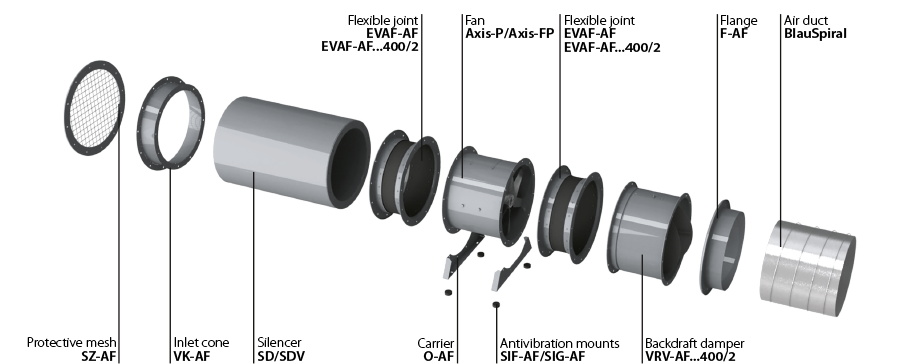
| COMPLETE SOLUTIONS FOR AXIAL FANS | ||
 |
||
| INSTALLATION EXAMPLE OF AXIAL FANS ON ROOFTOP | ||
 |
||
| FAN INSTALLATION INTO AN AIR DUCT SYSTEM
To ensure a uniform air flow, the fan should be preceded by a straight duct section with a cross-section area equal to half of that of the fan. The length of the duct section should be 3 ÷ 4 D (D is the inner diameter of the fan). The length of the straight duct section downstream of the fan should be 1.5 ÷ 2 D.Reduction of the recommended duct length values results in a drop of the fan pressure and performance. To reduce noise and vibration, use the EVAF-AF flexible joints.
Axial fans without upstream ducting must be equipped with a VK-AF inlet cone to improve the air flow parameters.
If the axial fan is a terminal device of the ventilation system (i.e. there is no downstream ducting), the unit must be equipped with a diffuser to reduce the air flow velocity and the fan dynamic pressure. Reduction of the air discharge velocity results in a significant reduction of shock losses which are proportional to the square of velocity decrement.The fan should not be equipped with a downstream contractor.
|
INSTALLATION NEAR BENDS
To install the fan directly downstream of a bend (elbow), use a curved section with a large bending radius or an array of internal guide vanes.
When changing from a smaller diameter to a larger one use a connector diffuser with the maximum opening angle of 12°.
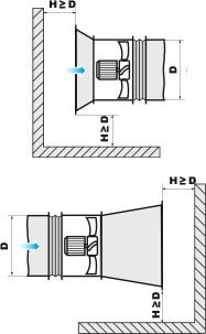
To ensure normal operation of the fan in an obstructed space, make sure to provide for a sufficient distance between the inlet and outlet flanges and the floor, walls, bulky equipment and obstacles.
|
|

 Domestic fans
 Industrial fans
 Single-room air handling units with heat recovery
 Air handling units
  Smoke extraction and ventilation
 Ventilation accessories
 Ventilation ducts and fittings
 Air distribution
 Measurement and control technology
 Ventilation sets and vents


