Blauberg CDTE E TP


- Description
- Modifications
- Downloads
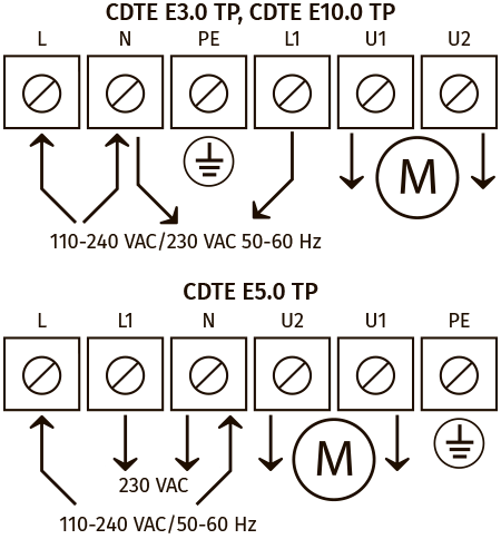
- Controller wiring diagram
| USE
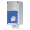
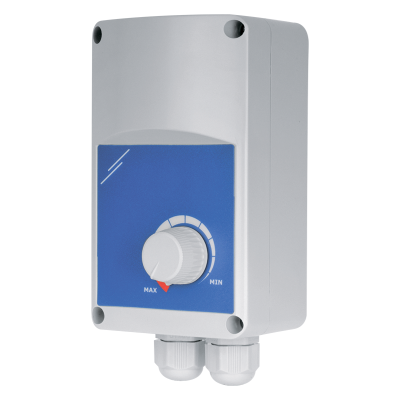
Applied in ventilation systems for speed switching ON/OFF and speed control of single phase power-controlled motors. Several fans can be controlled synchronously in case their total consumption current does not exceed the maximum controller current. DESIGN AND CONTROLThe controller casing is made of flame-retardant thermoplastic and fitted with ON/OFF knob with pilot light. The controller is featured with high efficiency and control accuracy. Output power is controlled from 30 to 100 % as a function of the control knob position. The minimum speed is set by means of the potentiometer at the PCB.The controller is equipped with an extra 230 V terminal for connection and controlling such external equipment as actuator-driven air dampers. PROTECTIONInput circuit of the speed controller has a thermal fuse for overload protection. The controller is fitted with a transient filter. |
MOUNTING
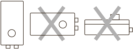
The controller is designed for indoor mounting. Installation shall be performed with respect to the free air circulation for inner circuit cooling. The controller is designed for vertical installation.Do not install the controller above the heaters and in bad air convection areas. DEVICE OPERATING POSITION
|

 Domestic fans
 Industrial fans
 Single-room air handling units with heat recovery
 Air handling units
  Smoke extraction and ventilation
 Ventilation accessories
 Ventilation ducts and fittings
 Air distribution
 Measurement and control technology
 Ventilation sets and vents
