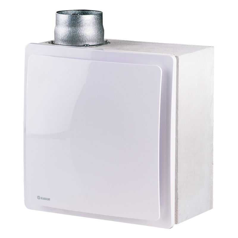
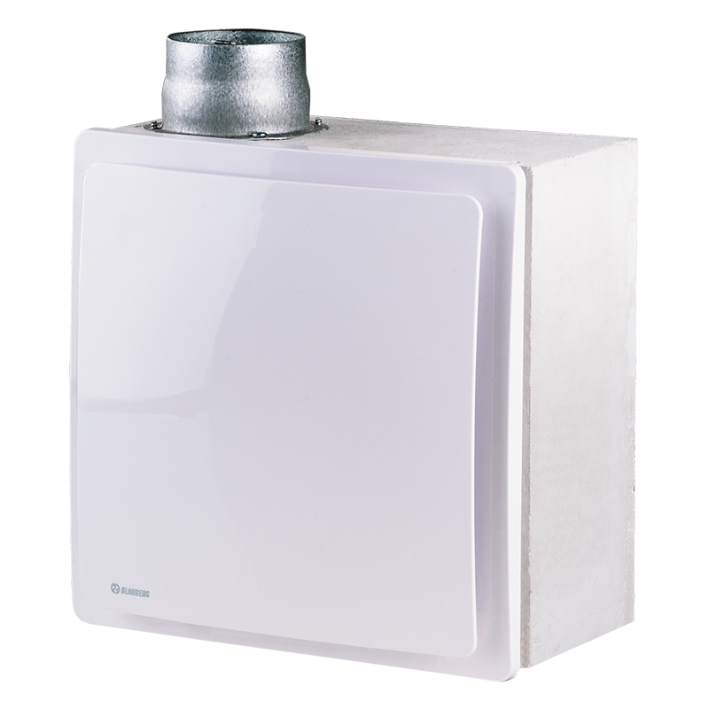
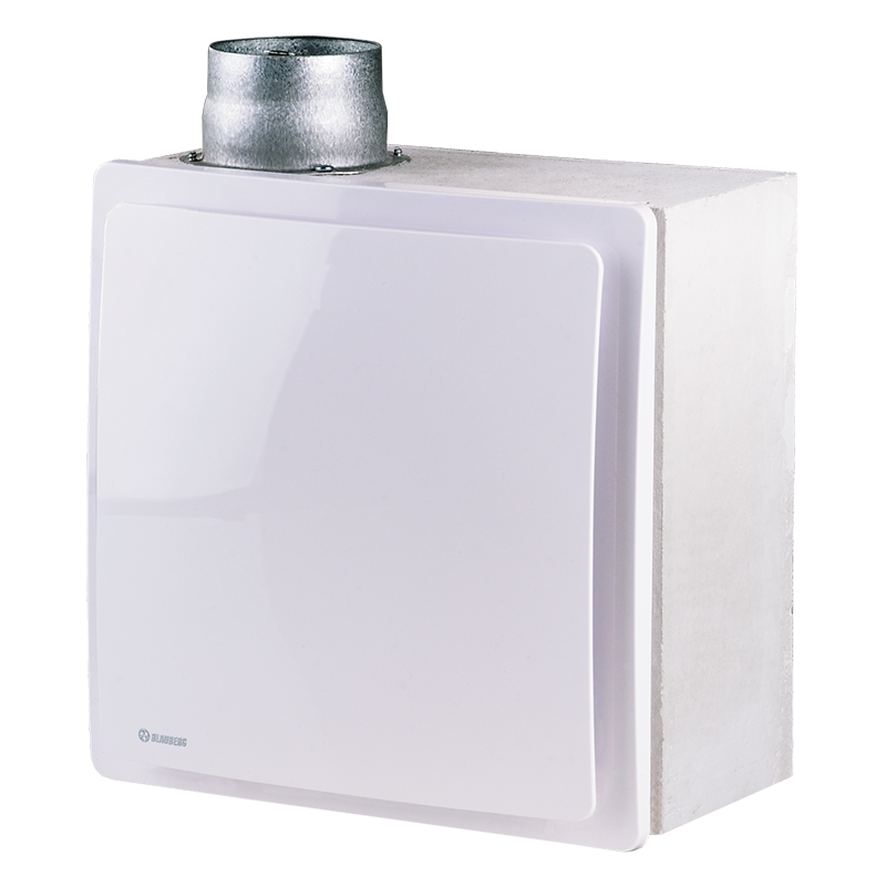
Blauberg Valeo-BF 35/60
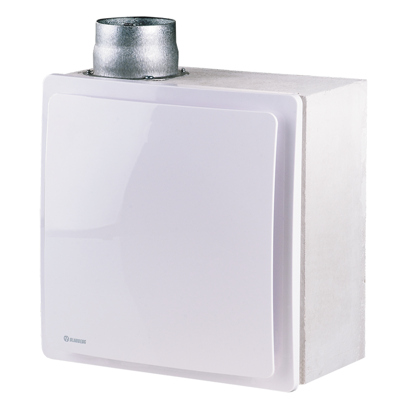

Mono-pipe ventilation exhaust centrifugal fans. Maximum air flow up to 63 m³/h.
 EAN
5f61ddc7af08b
- Description
- Characteristics
- Capacity diagram
- Downloads
- Options
Description
Description
| USE | SPEED CONTROL | ||||||||
| Extract ventilation systems installed in high-rise buildings and premises.For buildings with mono-pipe ventilation system.For mounting in kitchens and bathrooms.Surface wall or ceiling mounting. | Step speed control with an external speed controller, e.g. CDP-3/5 model which is available upon order.Wide range of intellectual controls programmable by set parameters (timer, adjustible timer, internal switch, humidity sensor). | ||||||||
| DESIGN | OPTIONS FOR 2 SPEED FAN MODELS | ||||||||
The fan consists of the fireproof casing BF for flush mounting and exhaust ventilation unit Valeo with a flat front panel.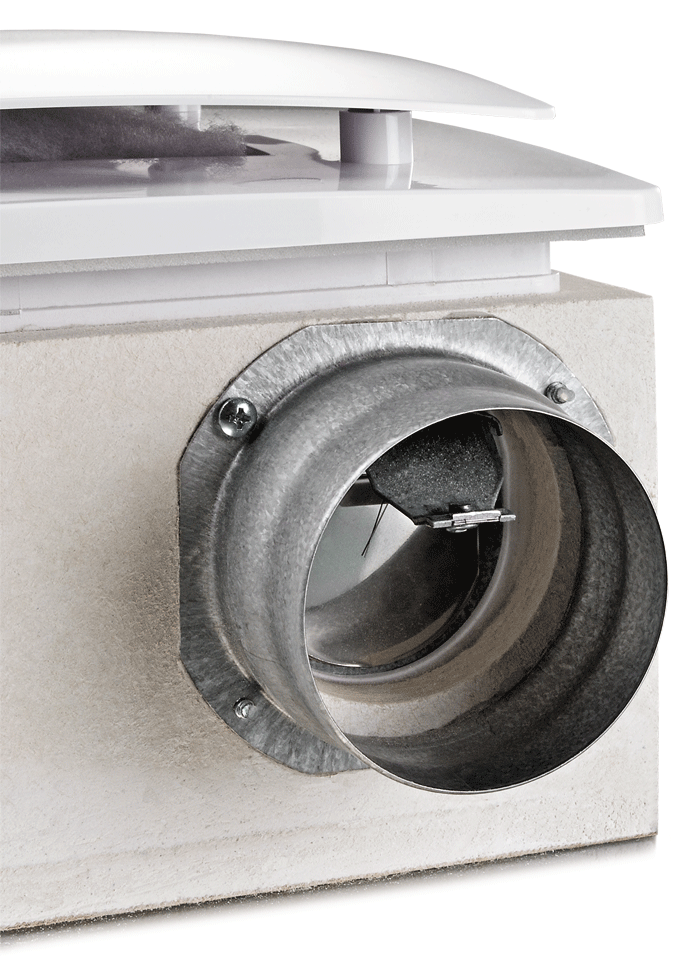 The casing is made of silicate plates based on calcium silicate and has high thermal insulating properties.Equipped with a fire-retarding damper to prevent fire and smoke expanding along air ducts. If temperature in the duct reaches 90°C the thermal fuse melts and closes the damper.When the fan is off the fire-retarding damper serves as a backdraft damper.The front panel is made of snow white UV-resistant plastic.Filter with filter class G4 for motor, impeller and ductwork system protection against soiling.The filter is easily accessible for service operations.Due to modern design and various colour modifications the front panel matches well with any interior.The casing is equipped with oblong slotted joints to facilitate mounting of the casing in true vertical position.If the casing is installed with some vertical deviations the special turnable grille conceals possible mounting inaccuracies.Power is supplied to the fan through a sealed electric lead-in on the casing and the ventilation unit is equipped with an airtight terminal block for connection to the wiring system.For room-to-room ventilation some ventilation unit modifications are equipped with extra spigots: Valeo-BFL – on the left; Valeo-BFR – on the right; Valeo-BFD – on the bottom.Ingress protection rating IP55. The casing is made of silicate plates based on calcium silicate and has high thermal insulating properties.Equipped with a fire-retarding damper to prevent fire and smoke expanding along air ducts. If temperature in the duct reaches 90°C the thermal fuse melts and closes the damper.When the fan is off the fire-retarding damper serves as a backdraft damper.The front panel is made of snow white UV-resistant plastic.Filter with filter class G4 for motor, impeller and ductwork system protection against soiling.The filter is easily accessible for service operations.Due to modern design and various colour modifications the front panel matches well with any interior.The casing is equipped with oblong slotted joints to facilitate mounting of the casing in true vertical position.If the casing is installed with some vertical deviations the special turnable grille conceals possible mounting inaccuracies.Power is supplied to the fan through a sealed electric lead-in on the casing and the ventilation unit is equipped with an airtight terminal block for connection to the wiring system.For room-to-room ventilation some ventilation unit modifications are equipped with extra spigots: Valeo-BFL – on the left; Valeo-BFR – on the right; Valeo-BFD – on the bottom.Ingress protection rating IP55. |
TIMER (VALEO-BF...Т) Depending on wiring connection the fan is off or runs permanently at low speed. The fan is turned to higher speed with external switch 50 s after activation. After turning the switch off the fan continues operating within 6 min at higher speed and then reverts to default operation mode.ADJUSTIBLE TIMER (VALEO-BF...ТR) Depending on wiring connection the fan is off or runs permanently at low speed. If the fan is turned on with an external switch it switches to higher speed 0 to 150 s after switch activation. After turning the fan off it continues running at higher speed within 2 to 30 minutes and then reverts to previous mode. The fan run-out time and delay time for higher speed are regulated with the internal regulator.INTERVAL SWITCH (VALEO-BF...I) Depending on wiring connection the fan is off or runs permanently at low speed. In interval mode regulated from 0,5 to 15 hours the fan switches periodically to higher speed for 10 minutes. The switch interval is adjusted with the internal regulator. If light in the room is turned with the external switch the fan switches to higher speed in 50 s. After light is off the fan reverts to interval mode operation.HUMIDITY SENSOR (VALEO-BF...H) Depending on wiring connection the fan is off or runs permanently at low speed. The fan switches to higher speed as relative humidity in the room increases from 60 % up to 90 % and switches off as humidity drops by 10 % below set level. If light in the room is turned on the fan switches to higher speed in 50 s. The run-out time is set by the internal regulator from 2 to 30 minutes. |
||||||||
| MOTOR | MOUNTING | ||||||||
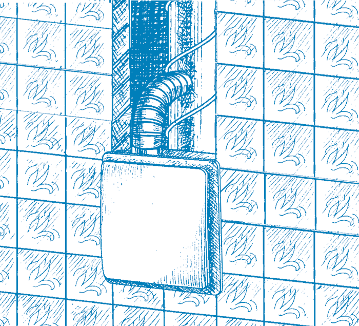
| Two- or three-speed motor with centrifugal impeller. Minimum energy demand.Galvanized steel impeller with forward curved blades.Automatic maintaining of constant air flow depending on variable air resistance of the duct.Balanced impeller ensures low-noise operation.Best aerodynamic characteristics due to special scroll casing design.Ball bearings provide long service life.The ventilation unit with motor is fixed inside the casing with special latches. | Installed in wall or ceiling during general construction works by mounting brackets supplied as a standard.Connection to main ventilation shaft with flexible air ducts.Exhaust spigot diameter 80 mm.Power is supplied to the fan through a sealed electric lead-in on the casing.After installation works cover the unit with a protecting cover to prevent dirt ingress.After finishing works install the ventilation unit inside the casing and connect it to wiring system. | ||||||||
| FRONT PANEL MODIFICATIONS | MOUNTING EXAMPLE | ||||||||
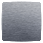
The standard snow white front panel can be replaced by the following models:
|
 |
||||||||
| HIGH-RISE MONO-PIPE VENTILATION SYSTEM ARRANGEMENT EXAMPLE | |||||||||
| The mechanical centralized mono-pipe exhaust ventilation system for kitchens and bathrooms based on Valeo-BF fans in fireproof casing with fire-retarding damper is specially designed for high-rise residential premises with high fire safety requirements. The inter-floor fire dampers are installed in the ventilation shaft to prevent fire and smoke extension in case of fire.Fresh air is supplied to bedrooms, children's room or living rooms through window or wall vents. Vent modifications with air volume regulation are available. | Stale air is extracted by exhaust fans from the room through inside doors or door grilles in the kitchen, bathroom or WC.This ventilation system arrangement ensures non-stop controllable air circulation in the room, comfortable microclimate and high fire safety. | ||||||||
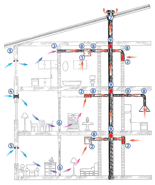 |
1 – Exhaust fan Valeo-BFD with extra spigot for room-to-room ventilation.2 – Exhaust fan Valeo-BF.3 – BLAUBERG wall grille, DECOR series.4 – BLAUBERG wall vent, WMH series.5 – BLAUBERG window vent, FHM series.6 – BLAUBERG ventilation door grilles, DECOR series.7 – Central ventilation shaft.8 – Flexible thermal-resistant air ducts for connection of exhaust fans to the central ventilation shaft.9 – Inter-floor fire damper. | ||||||||
Characteristics
Characteristics
Capacity diagram
Capacity diagram
Documents archieve
Documents archieve
Modifications
Modifications

 Domestic fans
 Industrial fans
 Single-room air handling units with heat recovery
 Air handling units
  Smoke extraction and ventilation
 Ventilation accessories
 Ventilation ducts and fittings
 Air distribution
 Measurement and control technology
 Ventilation sets and vents
