Domestic fans
 Industrial fans
 Single-room air handling units with heat recovery
 Air handling units
  Smoke extraction and ventilation
 Ventilation accessories
 Ventilation ducts and fittings
 Air distribution
 Measurement and control technology
 Ventilation sets and vents
Blauberg KOMFORT EC DBW 550 R S21
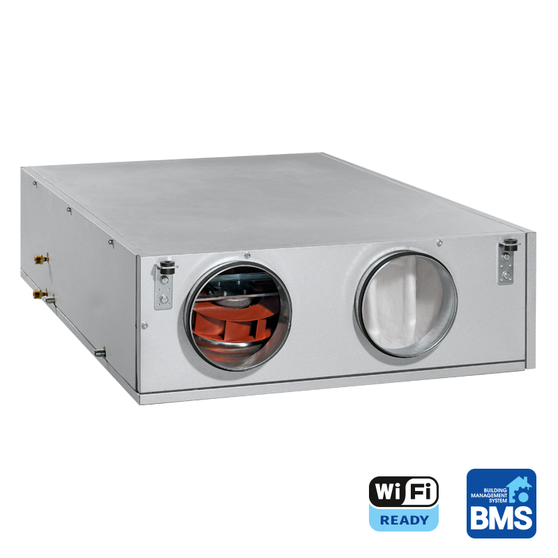


Maximum air flow up to 608 m³/h.
 EAN4058448071027
 - Description
- Characteristics
- Capacity diagram
- Downloads
- Designation key
- BIM
- Accessories
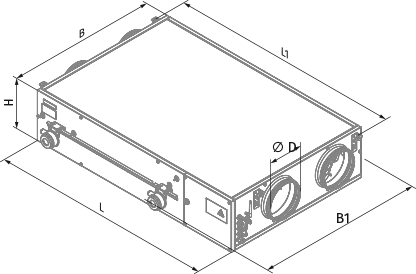
- Dimensions
- Additional characteristics
| FEATURES
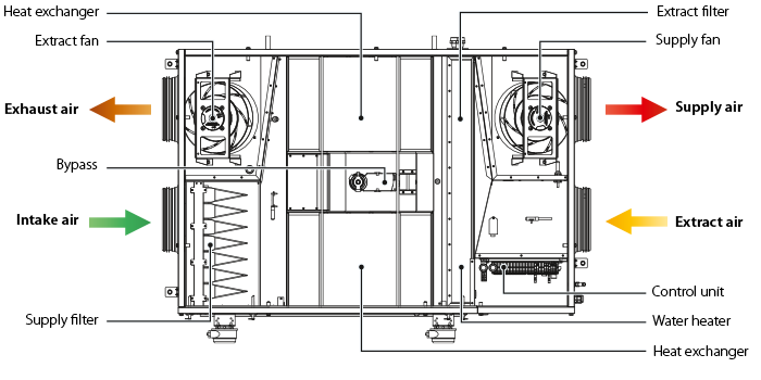
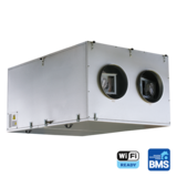
Air handling units for efficient supply and exhaust ventilation in flats, houses, cottages and other buildings. Heat recovery minimises ventilation heat losses. Provide controllable air exchange to create the best suitable indoor microclimate. Compatible with round Ø 200, 250, 315, 400 mm round air ducts. DESIGNThe casing is made of double-skinned aluzinc panels, internally filled with 20 mm mineral wool layer for heat and sound insulation. The casing has fixing brackets with vibration absorbing connectors for easy installation. The spigots for connection to the air ducts are located at the side of the unit and are rubber sealed for airtight connection to the air ducts. The service panel ensures easy access to the internals for cleaning, filter replacement and other maintenance operations. |
High-efficient external rotor EC motors and centrifugal impellers with backward curved blades are used for air supply and exhaust. EC motors have the best power consumption to air flow ratio and meet the latest demands concerning energy saving and high-efficient ventilation. EC motors are featured with high performance, low noise level and totally controllable speed range. Dynamically balanced impellers. |
||||||||||||||||||||||||||||||||||||||||||||||||||||||||||||||||||
| KOMFORT EC DBW... 550/900 | |||||||||||||||||||||||||||||||||||||||||||||||||||||||||||||||||||
|
|
|||||||||||||||||||||||||||||||||||||||||||||||||||||||||||||||||||
HEAT RECOVERY
The air flows are completely separated in the heat exchanger. Thus smells and contaminants are not transferred from the extract air to the supply air. Heat recovery is based on heat and/or humidity transfer through the heat exchanger plates. In the cold season supply air is heated in the heat exchanger by transferring the heat energy of warm and humid extract air to the cold fresh air. Heat recovery minimizes ventilation heat losses and heating costs respectively. In the warm season the heat exchanger performs reverse and intake air is cooled in the heat exchanger by the cool extract air. That reduces operation load on air conditioners and saves electricity. AIR HEATERThe unit is equipped with a water (glycol) heater for operation at low outside air temperature. The integrated water heater is activated to warm up supply air flow if set indoor air temperature may not be reached by means of heat recovery only. Heat medium temperature control ensures supply air temperature maintaining. The air temperature sensor downstream of the waterheating coils and the return water temperature sensor are used for freezing protection of the water heater. BYPASSThe units are equipped with a bypass for summer ventilation (room cooling by cool air from outside) and heat exchanger freeze protection. AIR FILTRATIONThe built-in G4 supply filter and G4 extract filter provide air filtration. The F7 supply filter (specially ordered accessory) may be used for efficient supply air filtration. MOUNTINGMounting to the ceiling with fixing brackets. The correct mounted unit must provide free condensate collection and drainage as well as good access for servicing and filter replacement. Access for servicing and cleaning the filter: from the right or left side panel, depending on the unit modification. |
CONTROL AND AUTOMATION
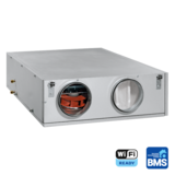
The units are equipped with an S21 integrated automation system. The remote control panel is not included in the delivery set (available separately). The S21 controller allows integrating the unit into the Smart Home system or BMS (Building Management System). The unit can be controlled by the Blauberg AHU mobile application via Wi-Fi.
AUTOMATION FUNCTIONS
Option: function is available when purchasing the appropriate accessory (see the "Accessories" tab). |
||||||||||||||||||||||||||||||||||||||||||||||||||||||||||||||||||