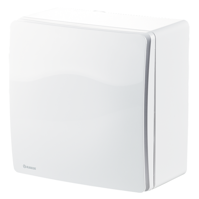
Blauberg Valeo-E 35/60
 EAN4058448020186
 - Description
- Characteristics
- Capacity diagram
- Downloads
- Modifications
- Dimensions
- Designation key
- Accessories
| USE |  |
|
Exhaust ventilation systems installed in high-rise buildings and premises.For buildings with a mono-pipe ventilation system.For mounting in kitchens and bathrooms.Surface wall or ceiling mounting. |
|
| DESIGN | |
|
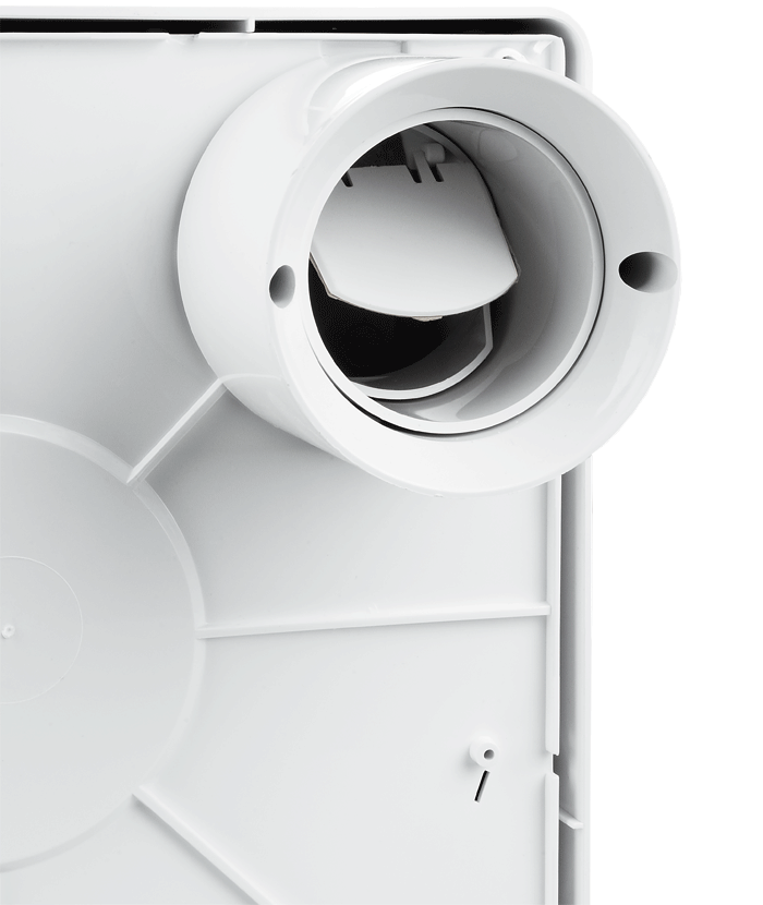
The fan consists of a plastic casing for surface mounting and an exhaust ventilation unit Valeo with a flat front panel.The casing is made of durable ABS plastic and fitted with a gravity backdraft damper to prevent backdrafting.
The front panel is made of snow-white UV-resistant plastic.Filter with filter class G4 for motor, impeller and ductwork system protection against soiling.The filter is easily accessible for service operations.Due to modern design and various colour modifications the front panel matches well with any interior.The casing is equipped with oblong slotted joints to facilitate mounting of the casing in true vertical position.Power is supplied to the fan through a sealed electric lead-in on the casing and the ventilation unit is equipped with an airtight terminal block for connection to the wiring system.Exhaust spigot diameter 80 mm.Ingress protection rating IP55. |
|
| OPTIONS | |
|
TIMER (VALEO-E...Т) |
|
| MOTOR | SPEED CONTROL |
|
Two-speed motor with a centrifugal impeller. Minimum energy demand.The impeller has forward curved blades.Automatic maintaining of constant air flow depending on variable air resistance of the duct.Balanced impeller ensures low-noise operation.Best aerodynamic characteristics due to special scroll casing design.Ball bearings provide long service life.The ventilation unit with a motor is fixed inside the casing with special latches. |
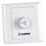
Step speed control with an external speed controller, e.g. CDP-3/5 model which is available upon order.Wide range of intellectual controls programmable by set parameters (timer, adjustable timer, internal switch, humidity sensor). |
| MOUNTING | MOUNTING EXAMPLE |
|
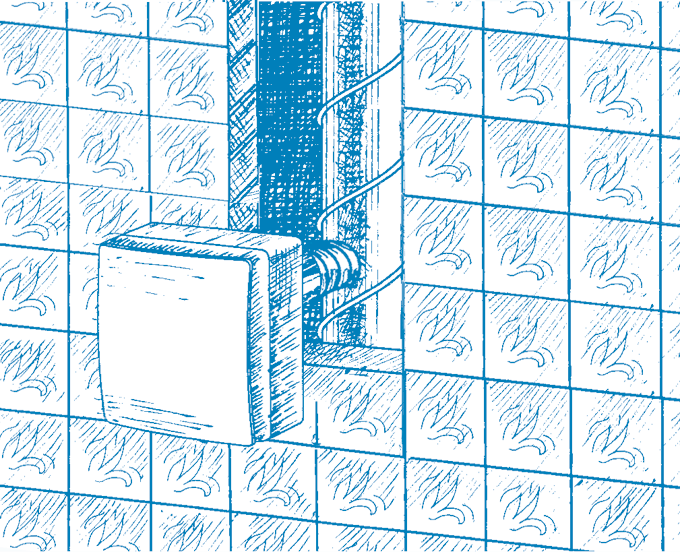
Flexible air ducts connected to the ductwork system and wiring are routed to the fan through the wall or ceiling.After finishing works a flexible air duct is fixed on the fan spigot with clamps.Power is supplied to the fan through a sealed electric lead-in on the casing.The casing is installed at site with dowels and is adjusted vertically with oblong slotted joints.The ventilation unit connected to the wiring system is installed in the mounted and fixed casing. |
 |
| HIGH-RISE MONO-PIPE VENTILATION SYSTEM ARRANGEMENT EXAMPLE | |
|
The mechanical centralized mono-pipe exhaust ventilation system for kitchens and bathrooms based on Valeo-E fans is specially designed for high-rise residential premises.Fresh air is supplied to bedrooms, children's room or living rooms through windows or wall vents. Vent modifications with air volume regulation are available. |
Stale air is extracted from the room by the exhaust fans through the inside doors or door grilles in the kitchen, bathroom or WC.This ventilation system arrangement ensures non-stop controllable air circulation in the room, comfortable microclimate and high fire safety. |
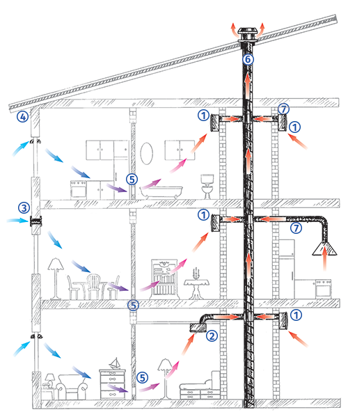 |
1 – Exhaust fan Valeo-E (surface mounting).2 – Exhaust fan Valeo-E (ceiling mounting).3 – BLAUBERG wall vent, WMH series.4 – BLAUBERG window vent, FHM series.5 – BLAUBERG ventilation grilles, DECOR series.6 – Central ventilation shaft.7 – Flexible air ducts for connection of exhaust fans to the central ventilation shaft, e.g. BLAUBERG air ducts, Blauflex series. |
| Parameter | Valeo-E 35/60 (1 speed) |
Valeo-E 35/60 (2 speed) |
Valeo-E 35/60 T (1 speed) |
Valeo-E 35/60 T (2 speed) |
Valeo-E 35/60 H (1 speed) |
Valeo-E 35/60 H (2 speed) |
Valeo-E 35/60 I (1 speed) |
Valeo-E 35/60 I (2 speed) |
Valeo-E 35/60 TR (1 speed) |
Valeo-E 35/60 TR (2 speed) |
Measurement unit |
|---|---|---|---|---|---|---|---|---|---|---|---|
| Speed | I | II | I | II | I | II | I | II | I | II | - |
| Voltage | 220-240 | 220-240 | 220-240 | 220-240 | 220-240 | 220-240 | 220-240 | 220-240 | 220-240 | 220-240 | V |
| Frequency | 50 | 50 | 50 | 50 | 50 | 50 | 50 | 50 | 50 | 50 | Hz |
| Current | 0.12 | 0.14 | 0.12 | 0.14 | 0.12 | 0.14 | 0.12 | 0.14 | 0.12 | 0.14 | A |
| Power | 15 | 25 | 15 | 25 | 15 | 25 | 15 | 25 | 15 | 25 | W |
| Cable cross section | 3×1.5 | 3×1.5 | 3×1.5 | 3×1.5 | 3×1.5 | 3×1.5 | 3×1.5 | 3×1.5 | 3×1.5 | 3×1.5 | mm² |
| Maximum air flow | 10 | 18 | 10 | 18 | 10 | 18 | 10 | 18 | 10 | 18 | l/s |
| Maximum air flow | 35 | 63 | 35 | 63 | 35 | 63 | 35 | 63 | 35 | 63 | m³/h |
| Sound pressure level | 27* | 36* | 27* | 36* | 27* | 36* | 27* | 36* | 27* | 36* | dBА |
| Max. operating temperature | +50 | +50 | +50 | +50 | +50 | +50 | +50 | +50 | +50 | +50 | °С |
| Motor IP rating | IP55 | IP55 | IP55 | IP55 | IP55 | IP55 | IP55 | IP55 | IP55 | IP55 | - |
| EC motor | no | no | no | no | no | no | no | no | no | no | - |
| Casing material | plastic | plastic | plastic | plastic | plastic | plastic | plastic | plastic | plastic | plastic | - |
| Outdoor mounting | no | no | no | no | no | no | no | no | no | no | - |
| Air duct | for round air ducts | for round air ducts | for round air ducts | for round air ducts | for round air ducts | for round air ducts | for round air ducts | for round air ducts | for round air ducts | for round air ducts | - |
| Design | centrifugal | centrifugal | centrifugal | centrifugal | centrifugal | centrifugal | centrifugal | centrifugal | centrifugal | centrifugal | - |
| Type | Exhaust | Exhaust | Exhaust | Exhaust | Exhaust | Exhaust | Exhaust | Exhaust | Exhaust | Exhaust | - |
| Mounting | ceiling mounting, wall mounting | ceiling mounting, wall mounting | ceiling mounting, wall mounting | ceiling mounting, wall mounting | ceiling mounting, wall mounting | ceiling mounting, wall mounting | ceiling mounting, wall mounting | ceiling mounting, wall mounting | ceiling mounting, wall mounting | ceiling mounting, wall mounting | - |
| * | Sound pressure level measured in free space at a distance of 3 meters from the fan | Sound pressure level measured in free space at a distance of 3 meters from the fan | Sound pressure level measured in free space at a distance of 3 meters from the fan | Sound pressure level measured in free space at a distance of 3 meters from the fan | Sound pressure level measured in free space at a distance of 3 meters from the fan | Sound pressure level measured in free space at a distance of 3 meters from the fan | Sound pressure level measured in free space at a distance of 3 meters from the fan | Sound pressure level measured in free space at a distance of 3 meters from the fan | Sound pressure level measured in free space at a distance of 3 meters from the fan | Sound pressure level measured in free space at a distance of 3 meters from the fan | - |
- Selection method:
- Air capacity:
- Pressure:
- Air capacity: --
- Pressure: ---
| Modification name |
|---|
| Valeo-E 35/60 |
| Valeo-E 35/60 H |
| Valeo-E 35/60 I |
| Valeo-E 35/60 T |
| Valeo-E 35/60 TR |
| Modification name | Timer | Humidity sensor | Interval Timer | No extra functions | Adjustible timer |
|---|---|---|---|---|---|
| Valeo-E 35/60 | - | - | - |

|
- |
| Valeo-E 35/60 H | - |

|
- | - | - |
| Valeo-E 35/60 I | - | - |

|
- | - |
| Valeo-E 35/60 T |

|
- | - | - | - |
| Valeo-E 35/60 TR | - | - | - | - |

|
|
|
|
|
|
|
|
|
|
|
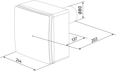
| Valeo-E | 35/60 |
TR |
| Model | Air flow according to speed | Option |

 Domestic fans
 Industrial fans
 Single-room air handling units with heat recovery
 Air handling units
  Smoke extraction and ventilation
 Ventilation accessories
 Ventilation ducts and fittings
 Air distribution
 Measurement and control technology
 Ventilation sets and vents