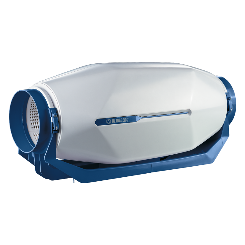
Blauberg inWave 100/125 (125 spigot)
 EAN
EAN - Description
- Characteristics
- Capacity diagram
- Downloads
- Designation key
- Accessories
- Dimensions
- Additional characteristics
| USE | |
|
Supply and extract ventilation systems installed in various premises with high requirements to the noise level.For ventilation air ducts requiring high pressure, powerful air flow and low noise level. |
Compatible with ∅ 100 up to ∅ 160 mm air ducts. |
| DESIGN | MOUNTING |
|
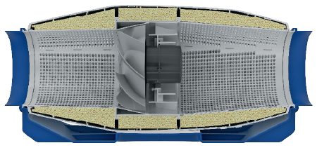
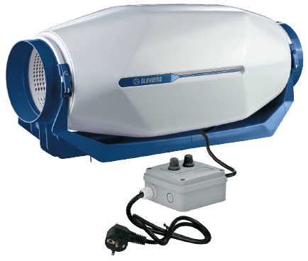
The casing is made of high-quality durable plastic, internally filled with 50 mm mineral wool thermal- and sound-insulating layer.Special inner perforation of the casing and sound-insulating material are designed for wide-frequency sound absorbing.Mixed-flow impeller made of high-quality plastic.The diffusor, the specially profiled impeller and directing vanes provide high performance and powerful pressure combined with low noise operation.External airtight terminal block on the fan casing for power supply.Mounting brackets on the fan casing for mounting to the floor, to the wall or ceiling. |
Due to its compact design the fan is the ideal solution for mounting in limited spaces.The fan is suitable for mounting in any section of the ventilation system from intake to the end of the ductwork.Wall or ceiling mounting with a special bracket on the fan casing. |
| MODIFICATIONS AND OPTIONS | |
|
T: turn-off delay timer adjustable from 2 to 30 minutes.US: three-position speed switch.FR1: smooth speed controller adjustable from 0 to 100 % and power cable with mains plug. |
|
 |
 |
| MOTOR | |
|
Single-phase high-efficient motor with low energy demand on ball bearings.Overheating protection due to built-in thermal switches.Motor ingress protection rating IPX4. |
|
| SPEED CONTROL |
G1: speed controller, temperature controller with external temperature sensor (cable length 4 m), power cable with mains plug.GI1: speed controller, temperature controller with integrated temperature sensor and power cable with mains plug.The G1 and GI1 modifications enable automatic speed control depending on indoor temperature. The optimal ventilation solution for premises requiring permanent temperature control as greenhouses, orangeries, etc. |
|
Speed selection with a built-in speed switch (US option) or an external multi-speed controller (specially ordered accessory). |
| Parameter | inWave 100/125 (125 spigot) min |
inWave 100/125 (125 spigot) mid |
inWave 100/125 (125 spigot) max |
Measurement unit |
|---|---|---|---|---|
| Spigot | 125 | 125 | 125 | mm |
| Speed | min | mid | max | - |
| Voltage | 230 | 230 | 230 | V |
| Phase | 1 | 1 | 1 | ˜ |
| Frequency | 50 | 50 | 50 | Hz |
| Current | 0.14 | 0.14 | 0.16 | A |
| Power | 31 | 33 | 34 | W |
| RPM | 1552 | 1952 | 2356 | min-1 |
| Maximum air flow | 46 | 60 | 89 | l/s |
| Maximum air flow | 164 | 216 | 320 | m³/h |
| Sound pressure level at 3 m | 20 | 22 | 28 | dBА |
| Max. operating temperature | –25…+55 | –25…+55 | –25…+55 | °С |
| Motor IP rating | IP20 | IP20 | IP20 | - |
| Ingress protection rating | IPX4 | IPX4 | IPX4 | - |
| EC motor | no | no | no | - |
| Casing material | plastic | plastic | plastic | - |
| Outdoor mounting | no | no | no | - |
| Sound-insulated casing | yes | yes | yes | - |
| Air duct | for round air ducts | for round air ducts | for round air ducts | - |
| Design | mixed-flow | mixed-flow | mixed-flow | - |
| Type | Exhaust, Supply | Exhaust, Supply | Exhaust, Supply | - |
| Weight | 5 | 5 | 5 | kg |
| Mounting | Inline | Inline | Inline | - |
| ErP | 2018 | 2018 | 2018 | - |
- Selection method:
- Air capacity:
- Pressure:
- Air capacity: --
- Pressure: ---
| Series | Duct diameter [mm] | Options |
| inWave | 100/125; 150/160 | T: turn-off delay timer adjustable from 2 to 30 minutes US: three-position speed switch FR1: smooth speed controller adjustable from 0 to 100 % and power cable with mains plug G1: speed controller, temperature controller with external temperature sensor, power cable with mains plug W1: power cable with mains plug |

| Model | Overall dimensions [mm] | |||
| ∅ D | H | L | W | |
| inWave 100/125 (spigot 125 mm) | 124 | 273 | 679 | 253 |
| Sound power level, A-weighted | Total | Octave frequency bands [Hz] | LpA 3 m | LpA 1 m | |||||||
| 63 | 125 | 250 | 500 | 1000 | 2000 | 4000 | 8000 | ||||
| LwA to inlet [dBA] | 54 | 31 | 49 | 52 | 43 | 37 | 34 | 37 | 30 | 34 | 44 |
| LwA to outlet [dBA] | 52 | 26 | 44 | 51 | 41 | 33 | 32 | 37 | 31 | 32 | 42 |
| LwA to environment [dBA] | 48 | 28 | 45 | 45 | 37 | 32 | 28 | 28 | 22 | 28 | 38 |

 Domestic fans
 Industrial fans
 Single-room air handling units with heat recovery
 Air handling units
  Smoke extraction and ventilation
 Ventilation accessories
 Ventilation ducts and fittings
 Air distribution
 Measurement and control technology
 Ventilation sets and vents