Domestic fans
 Industrial fans
 Single-room air handling units with heat recovery
 Air handling units
  Smoke extraction and ventilation
 Ventilation accessories
 Ventilation ducts and fittings
 Air distribution
 Measurement and control technology
 Ventilation sets and vents
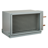
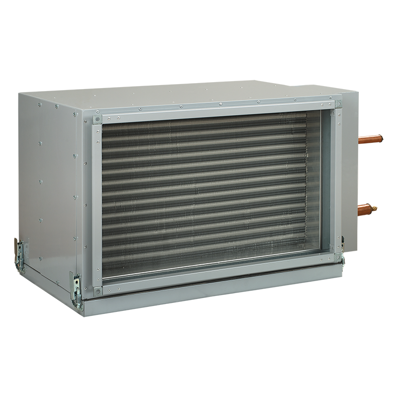
Blauberg KFK 50x30-3


- Description
- Characteristics
- Downloads
- Designation key
- Dimensions
- Air pressure losses
- Calculation diagram
| USE
Supply air cooling for ventilation systems in various premises. Suitable for installation into supply or air handling units to provide air cooling. DESIGNGalvanized steel casing. The cooling elements are made of copper tubes and aluminum plates. Available in three-coil modifications and rated for operation with R123, R134a, R152a, R404a, R407c, R410a, R507, R12, R22, R32 refrigerants. Polypropylene droplet separator and drain pan for condensate drainage and removal included. Droplet separator operates efficiently at air flow below 4 m/s.
|
MOUNTING
Only horizontal mounting by means of flanged connection. Condensate drainage must be provided. Air filter must be installed upstream of the cooling unit to prevent the unit soiling. Mounting position must ensure uniform air flow distribution through the entire cross section. Installation upstream or downstream of the supply fan. The minimum air duct length downstream of the fan must be 1-1.5 m to ensure air flow stabilization. The maximum cooling capacity is attained if the cooling unit is connected on counter-flow basis. The attached charts are valid for counter-flow connection. While mounting the cooling unit provide condensate drainage through the U-trap. The U-trap height must be selected with respect to the total fan pressure, refer to the table and diagram below.
For a proper and safe operation of the cooling unit it should be connected to a control system for integral control and automatic cooling capacity regulation. |
/KFK-counter-air-flow-connection-200.png)
/KFK-air-flow-streamwise-connection-187.png)
/KFK-U-trap-150.png)
/KFK-dimensions-400.png)
/KFK-pressure-loss-400-EN.png)
/KFK-50x30-3-graph-1100-EN.png)