Domestic fans
 Industrial fans
 Single-room air handling units with heat recovery
 Air handling units
  Smoke extraction and ventilation
 Ventilation accessories
 Ventilation ducts and fittings
 Air distribution
 Measurement and control technology
 Ventilation sets and vents
Blauberg KOMFORT EC SB 250 S21


 EAN4058448058127
 - Description
- Characteristics
- Capacity diagram
- Downloads
- Designation key
- BIM
- Accessories
- Dimensions
- Additional characteristics
| FEATURES
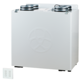
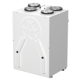
Air handling units for efficient energy saving supply and exhaust ventilation in flats, houses, cottages and other premises. Heat and humidity recovery minimizes ventilation heat losses during cold season and reduces air conditioner load during hot season. Controllable air exchange for creating the best suitable indoor microclimate. Compatible with round Ø 125, 160 or 200 mm air ducts. FANSThe units are equipped with high-efficient EC motors with an external rotor and a centrifugal impeller with backward curved blades. EC motors have the best power consumption to air capacity ratio and meet the latest demands concerning energy saving and high-efficient ventilation. EC motors are featured with high performance, low noise level and optimum control across the entire speed range. The impellers are dynamically balanced. BYPASSThe KOMFORT EC SB(-E) units are equipped with a bypass for ventilation (air cooling by the cool air from outside). |
The casing is made of double-skinned polymer-coated steel panels, internally filled with 20, 30, 40 mm (depending on the unit model) mineral wool layer for heat- and sound-insulation. The unit is equipped with a hinged service panel to enable convenient access for maintenance or repair operations. The spigots are located at the top of the unit and are equipped with rubber seals for airtight connection to the air ducts. AIR FILTRATIONThe built-in F7 filter provides efficient supply air filtration. The G4 filter is used for extract air cleaning. In the KOMFORT EC SB(E) 250 units, the supply air is cleaned by the G4 filter (F7 filter optionally available). |
|||||||||||||||||||||||||||||||||||||||||||||||||||||||||||||||||||||||||||||||||||||||||||||
_250(-E)-design-550-EN-2021-11.png) |
||||||||||||||||||||||||||||||||||||||||||||||||||||||||||||||||||||||||||||||||||||||||||||||
HEAT RECOVERY (-E)_S14_S21-heat-exchanger-112.png)
The KOMFORT EC S(B) unit is equipped with a plate counter-flow polystyrene heat exchanger for heat recovery. The unit condensate is collected and drained to the drain pan under the heat exchanger.
The KOMFORT EC S(B)-E unit is equipped with an enthalpy plate counter-flow heat exchanger for energy (heat and humidity) recovery. Due to humidity recovery condensate is not generated in the enthalpy heat exchanger. The air flows are completely separated in the heat exchanger. Thus smells and contaminants are not transferred from the extract air to the supply air. Heat recovery is based on heat and/or humidity transfer through the heat exchanger plates. In the cold season supply air is heated in the heat exchanger by transferring the heat energy of warm and humid extract air to the cold fresh air. Heat recovery minimizes ventilation heat losses and heating costs respectively. In the warm season the heat exchanger performs reverse and intake air is cooled in the heat exchanger by the cool extract air. That reduces operation load on air conditioners and saves electricity. When the indoor and outdoor temperature difference is insignificant, heat recovery is not reasonable. In this case the heat exchanger can be temporary replaced with a summer block for the warm season (available as a specially ordered accessory). |
MOUNTING
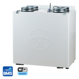
The units are designed for wall or floor mounting. Universal casing design provides either left-handed or right-handed unit installation. CONTROL AND AUTOMATIONThe KOMFORT EC S(B)(-E) S21 units are equipped with an integrated automation system. The remote control panel is not included in the delivery set (available separately). The S21 controller allows integrating the unit into the Smart Home system or BMS (Building Management System). The unit can be controlled by the Blauberg AHU mobile application via Wi-Fi.
The KOMFORT EC S(B)(-E) S14 units have an integrated automation system with a wall-mounted control panel S14 with a LED indication. |
|||||||||||||||||||||||||||||||||||||||||||||||||||||||||||||||||||||||||||||||||||||||||||||
| AUTOMATION FUNCTIONS | ||||||||||||||||||||||||||||||||||||||||||||||||||||||||||||||||||||||||||||||||||||||||||||||
|
||||||||||||||||||||||||||||||||||||||||||||||||||||||||||||||||||||||||||||||||||||||||||||||
(-E)_S14_S21-qr-code-google-play-100.png)
(-E)_S14_S21-qr-code-itunes-100-EN.png)
(-E)_S14_S21-modbus-100.png)


(-E)_160-350-550-S14_S21-dimensions-400-2021-11.png)
(-E)_250_S14_S21-graph-400-EN-2021-11.png)