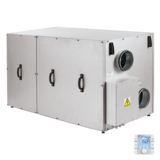
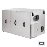
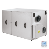
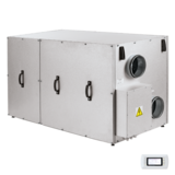
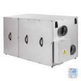
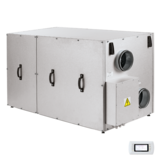
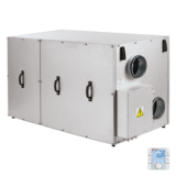
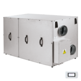
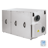
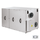
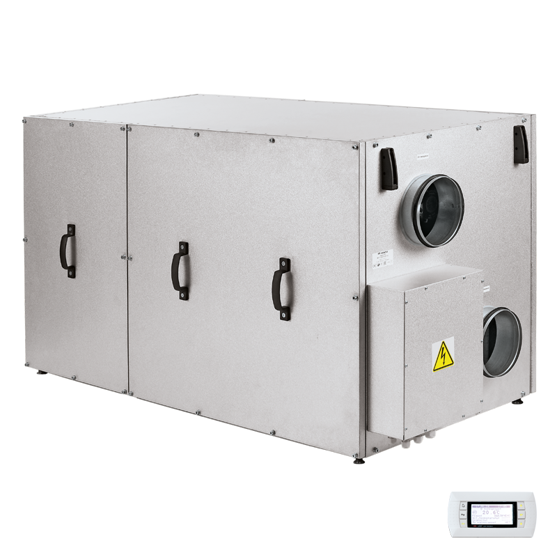
Blauberg KOMFORT Roto EC LEHP 900 S18
 EAN
EAN - Description
- Characteristics
- Downloads
- Designation key
- Accessories
- Dimensions
- Capacity diagram
- Heat pump
| FEATURES
Air handling units for efficient supply and exhaust ventilation in flats, houses, cottages and other buildings. For arranging of controlled energy saving ventilation systems. Controllable air exchange for creating the best suitable indoor microclimate. A fully integrated heat pump eliminates the need for installing the indoor and outdoor units of an air conditioner inside the treated space and on the building face. The heated or cooled air is distributed via a duct system to individual rooms for air distribution through air diffusers which gives the building a clean aesthetic look both inside and outside. Compatible with round Ø 160 and 250 mm air ducts. DESIGNThe casing load-bearing structure consists of three-layer zinc aluminium panels with a 25 mm fibreglass interlayer for noise and heat insulation. The spigots are located at the sides of the unit and are equipped with rubber seals for airtight connection to the air ducts. Specially designed removable side panels provide easy access to all the internal components of the air handling unit and reduce maintenance space requirements. KOMFORT Roto EC LHP: models with a rotary regenerator and heat pump with no preheating. KOMFORT Roto EC LEHP: models with a rotary regenerator, heat pump and a supply air preheater. |
High-efficient external rotor EC motors and centrifugal impellers are used for air supply and exhaust. EC motors have the best power consumption to air flow ratio and meet the latest demands concerning energy saving and high-efficient ventilation. EC motors are featured with high performance, low noise level and totally controllable speed range. Dynamically balanced impellers. AIR FILTRATIONThe built-in G4 supply filter and G4 extract filter provide air filtration. A F7 supply filter (specially ordered accessory) may be used for efficient supply air filtration. |
|
| KOMFORT ROTO EC L(E)HP 700/900 | ||
|
|
||
| TWO-STAGE HEAT ENERGY RECOVERY SYSTEM
Stage I – heat energy recovery in the rotary heat exchanger. Stage II – booster heating/booster cooling in the heat pump. HEAT RECOVERYThe unit has a high-efficient rotary aluminium heat exchanger. The rotary regenerator is a short, rotating cylinder, filled with corrugated aluminium sheet layers. The air streams flow through them. The band layers of the heat regenerator first come in contact with the supply and then with extract air flows. Therefore the band is alternatively warmed up and cooled down and the extract air heat and humidity are transferred to the cold intake air. This way heat recovery reduces heat losses in the cold season and reduces operation load for air conditioner in the warm season. The advantages of the rotary regenerator as compared to the plate heat exchangers include no condensate generation, maintaining comfort air humidity and high freeze resistance.
"Auto" mode: The unit runs in the automatic supply and exhaust mode maintaining a user-defined room temperature. "Heating" mode: The unit ensures supply and exhaust ventilation of the treated space maintaining the room temperature above a pre-set threshold. As soon as the room temperature drops below the pre-set threshold the heat exchanger and the heat pump are engaged (in the heating mode). "Cooling" mode: The unit ensures supply and exhaust ventilation of the treated space maintaining the room temperature below a pre-set threshold. As soon the room temperature exceeds the pre-set threshold the heat exchanger and the heat pump are engaged (in the cooling mode). "Heat Recovery" mode: The unit runs in the supply and exhaust mode maintaining the room temperature by means of the heat exchanger only without engaging the heat pump. This mode is enabled automatically while in the "Auto", "Heating" or "Cooling" mode if the heat exchanger alone is able to maintain the user-defined room temperature without engaging the heat pump. This mode can also be enabled manually via the unit controller menu or the S18 (pGD1) control panel. "Ventilation" mode: The unit ensures supply and exhaust ventilation of the treated space without maintaining a pre-set room temperature level. The heat exchanger and heat pump are disabled. Room temperature adjustment is not available. This operation mode is only available via the S18 (pGD1) control panel. "Defrosting" mode: Enabled automatically (on elapsing of a pre-set time interval and/or on reaching a temperature threshold) while in the "Auto" and "Heating" modes to prevent the heat pump heat exchanger freezing. While in the "Defrosting" mode the fans are disabled. Upon the "Defrosting" mode deactivation the unit reverts to the previous operation mode automatically. While in the "Defrosting" mode user-selectable operation modes are not available. "Pre-Heating" mode: While in the "Auto" or "Heating" modes at low ambient temperatures the supply air fed into the unit is warmed up by the electric pre-heater. This mode is enabled automatically upon the ambient temperature dropping below 8 °C. If the outdoor air temperature reaches above 8 °C the "Pre-Heating" mode is disabled. This mode is only available in factory configurations of the KOMFORT Roto EC LEHP models equipped with an electric heater. The "Pre-Heating" mode implementation in a KOMFORT Roto EC LHP requires upgrading the unit with a production electric heater (purchased separately) installed into the unit casing. The heater may only be installed by a service provider certified by the unit manufacturer. "Recirculation" mode: This optional mode requires upgrading the unit with an external recirculation valve (purchased separately). The recirculation mode is enabled automatically at subzero ambient temperatures allowing a considerable reduction of unit energy consumption due to a partial redirection of the extract air into the supply duct of the unit. |
AIR HEATER
The KOMFORT Roto EC LEHP unit is equipped with the optional posistor electric heater to warm up outdoor supply air at low temperatures. Pre-heating reduces the number of heat pump defrosting cycles thus increasing the overall operational efficiency of the air handling unit. The heater is divided into two active elements for reduced power electric power consumption while retaining sufficient heating capacity. CONTROL AND AUTOMATION
Limit Function: Reduces air flow automatically to maintain a user-defined temperature. If the unit cannot execute the user-defined room temperature setting after running in the "Auto" or "Heating" mode for 20 minutes the air flow rate (fan speed) is reduced automatically. The unit reverts to the original fan operation mode upon reaching the target air temperature as defined by the user. While in the "Limit Function" mode the air flow adjustment is not available. Warming-up: Blocks cold air supply into the premises in the "Auto" or "Heating" mode. The effect is achieved by warming up the heat pump heat exchanger in the supply air duct while the supply fan remains disabled. The "Warming-up" mode is enabled after the "Defrosting" mode as well as upon the first start if the outdoor air temperature is below +10 °C. Upon completion of the "Warmingup" cycle the unit reverts to the original "Auto" or "Heating" mode. Higher Speed: Increases air flow capacity automatically while in the "Cooling" mode to prevent excessive pressure build-up in the heat pump. The exhaust fan reverts to the initial speed once the pressure has dropped to normal. Smart Safe: Automatically protects the unit from operating outside the safe performance range. The unit is equipped with an intelligent hardware protection system ensuring its safe and reliable performance within the permissible range of ambient temperature conditions. Therefore, the unit is able to adjust operating parameters or disable certain units and assemblies to compensate for abnormal operating conditions in order to prevent equipment failure. Heat Pump Protection: Automatically prevents heat pump failure:
Serviceability: The design solutions provide for easy access to the unit parts and components, facilitate its maintenance and replacement of the consumables and wear parts and ensure high serviceability of the entire air handling unit. Fresh Air: Ensures clean air supply into the treated spaces. The unit is equipped with a G4 filter (F7 filter optional). The control system monitors the filter performance automatically and generates replacement signals as necessary. Ozone Protection: The heat pump utilizes the R410A high-tech two-component cooling agent which does not deplete the ozone layer. Save Energy: A comprehensive engineering and technical approach to reducing the unit energy consumption which comprises the following elements:
Low Noise: A comprehensive engineering and technical approach to reducing the unit noise levels during operation comprising the following elements:
Autorestart: The unit memorizes the current operation mode and restores it after a power outage. Simple Use: The units are pre-assembled at the factory and are ready for operation. The installation and maintenance costs are reduced to a bare minimum. The unit operation does not require any special training due to a clean-cut user-friendly interface. CO₂ Control: Maintains the CO₂ level in the treated space below a user-defined value. If the CO₂ level in the indoor space exceeds the pre-set value the air handling unit increases the air exchange rate automatically. This option is only available with the external CO₂ control sensor with a 0–10 V output signal (purchased separately). RH Control: Maintains the relative humidity level in the treated space below a user-defined value. Should the relative humidity become abnormally high the unit increases the air exchange rate automatically. This option is only available with the S17 (th-Tune) control panel in a special configuration or the external relative humidity control sensor with a 0–10 V output signal (purchased separately). Rapid Access to Set Mode: The larger the difference between the outdoor temperature and the pre-set indoor temperature, the faster the heat pump is activated. |
|
|
Unit operation in heat recovery and air heating ventilation mode |
Unit operation in heat recovery and air cooling ventilation mode |
|

 Domestic fans
 Industrial fans
 Single-room air handling units with heat recovery
 Air handling units
  Smoke extraction and ventilation
 Ventilation accessories
 Ventilation ducts and fittings
 Air distribution
 Measurement and control technology
 Ventilation sets and vents

HP/KOMFORT-Roto-EC-L(E)HP-700-900-design-886-EN.png)
HP/KOMFORT_Roto_EC_LE-LW-Recovery-En-2021-02.png)
HP/KOMFORT-Roto-EC-L(E)HP-Heat-pump.png)
HP/KOMFORT-Roto-EC-L(E)HP-S17.png)
HP/KOMFORT-Roto-EC-L(E)HP-S18.png)
HP/KOMFORT-Roto-EC-L(E)HP-heating-wiring.png)
HP/KOMFORT-Roto-EC-L(E)HP-emergency-recall.png)

HP/accessories/VKA-67.png)
HP/accessories/DPWC11200-68.png)
HP/KOMFORT-Roto-EC-L(E)HP-700-900-Dimension.png)
HP/graphs/KOMFORT-Roto-EC-LEHP-900-graph-400-EN.png)
HP/graphs/KOMFORT-Roto-EC-LEHP-900-heating-mode-500-EN.png)
HP/graphs/KOMFORT-Roto-EC-LEHP-900-cooling-mode-500-EN.png)
