Domestic fans
 Industrial fans
 Single-room air handling units with heat recovery
 Air handling units
  Smoke extraction and ventilation
 Ventilation accessories
 Ventilation ducts and fittings
 Air distribution
 Measurement and control technology
 Ventilation sets and vents
Blauberg WKH 125-2


- Description
- Characteristics
- Downloads
- Designation key
- Dimensions
- Air pressure loss
- Calculation diagram
| FEATURES
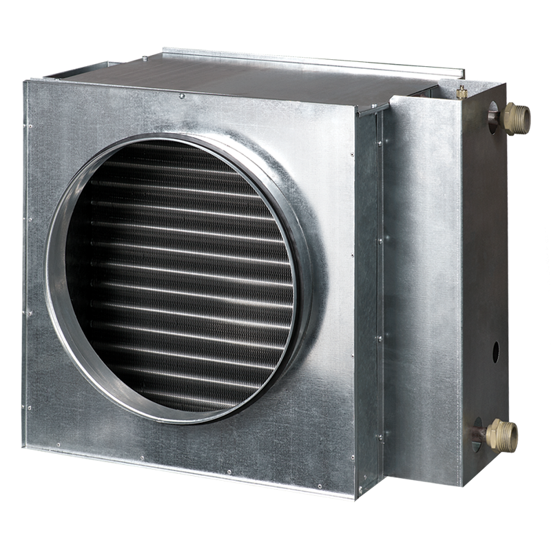
For warming up of supply air in ventilation systems installed in various premises. Suitable for installation in supply or air handling units to warm up the supply air flow. For indoor use only if water serves as a heat carrier. For outdoor use antifreezing mixture (ethylene glycol solution). Compatible with Ø 100 to 315 mm round air ducts. DESIGNGalvanized steel casing. Copper pipe manifold. Heat exchange surface made of aluminium plates. Airtight connection with air ducts due to rubber seals. Equipped with a nipple for the system deaeration. Outlet header is equipped with a spigot for installation of an immersion temperature sensor or freezing protection mechanism. Available in two- or four-row coil modifications. Suitable for operation at maximum operating pressure 1.6 MPa (16 bar) and maximum operating temperature +100 °C. |
MOUNTING
Fixing to round ducts with clamps. Any mounting position that ensures the heater deaeration. Install a filter upstream to the heater to protect heating elements against dirt ingress. Install the heater in front or behind the fan. In case of mounting behind the fan ensure a distance of not less than two connecting diameters for air flow stabilization and keep the maximum permissible air temperature inside the fan. Connect the heater on counter-flow basis, otherwise its capacity drops by 5–15 %. All the nomographic charts are rated for counter-flow connection. For correct and safe heater operation an automatic control and protection system is recommended, including the following functions:
|
|
|
|
||
| Parameter | WKH 125-2 | Measurement unit |
|---|---|---|
| Number of water coil rows | 2 | - |
| Weight | 4.5 | kg |
| Casing material | galvanized steel | - |
| Air duct | for rectangular air ducts | - |
| Connection diameter | 125 | mm |
| Series | Connected air duct diameter [mm] | Number of water (glycol) coil rows | |
| WKH | 100; 125; 150; 160; 200; 250; 315 | — | 2; 4 |
/WKH-dimensions-250.png)
| Model | Overall dimensions [mm] | ||||||||
| D | B | H | H2 | L | L1 | L2 | L3 | K | |
| WKH 125-2 | 125 | 350 | 240 | 150 | 300 | 82 | 43 | 220 | G 3/4” |
/WKH-air-pressure-loss-350-EN.png)
/graphs/WKH-100-125-2-graph-1000-EN.png)
|
How to use water heater diagrams. System Parameters: Air flow = 250 m³/h. Outside air temperature = -15 °C. Water temperature (in/out) = +90/+70 °C. The air flow is 250 m³/h and the air speed in the heater is 3.75 m/s ①. |
||
| To calculate the maximum air temperature find the intersection point of the air flow line ① with the rated outer temperature shown in blue line (e.g., -15 °C) and draw the line ② to the left until it crosses the water in/out temperature curve (e.g., +90/+70). From this point draw a vertical line to the supply air temperature downstream of the heater (+17.50 °C) ③. To calculate the heater power find the intersection point of the air flow ① with the rated winter temperature shown in red line (e.g., -15 °C) and draw the line ④ to the right until it crosses the water in/out temperature curve (e.g., +90/+70). From this point draw a vertical line to the heater power axis (3.25 kW) ⑤. | To calculate the required water flow in the heater prolong this line ⑥ downwards to the water flow axis (0.042 l/s). To calculate the water pressure drop in the heater find the intersection point of the line ⑥ with the pressure loss curve and prolong the line ⑦ to the right on the water pressure drop axis (2.9 kPa). |