Domestic fans
 Industrial fans
 Single-room air handling units with heat recovery
 Air handling units
  Smoke extraction and ventilation
 Ventilation accessories
 Ventilation ducts and fittings
 Air distribution
 Measurement and control technology
 Ventilation sets and vents
Blauberg WMG 1 1/2-25


- Description
- Characteristics
- Downloads
- Designation key
- Connection to water network
- Overall dimensions
- Mixing unit calculation diagram
| FEATURES
Smooth heating medium flow regulation and supply air set temperature maintaining in ventilation systems with water heating or cooling coils. Compatible with the WKH duct water heating coils and the KWK duct cooling coils. Compatible with all water heating or cooling coils installed in BLAUBOX supply units and KOMFORT air handling units. CONNECTION TO WATER CIRCUITConnection of the mixing unit to the water heating or cooling coils and to the water heating/cooling network through the pipes or flexible hoses of respective diameter, refer to the technical data table. In case of applying flexible hoses the mixing unit must be rigidly fixed. While installing the mixing unit the motor shaft must be installed horizontally. No mechanical loads from the pipes are allowed. |
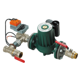
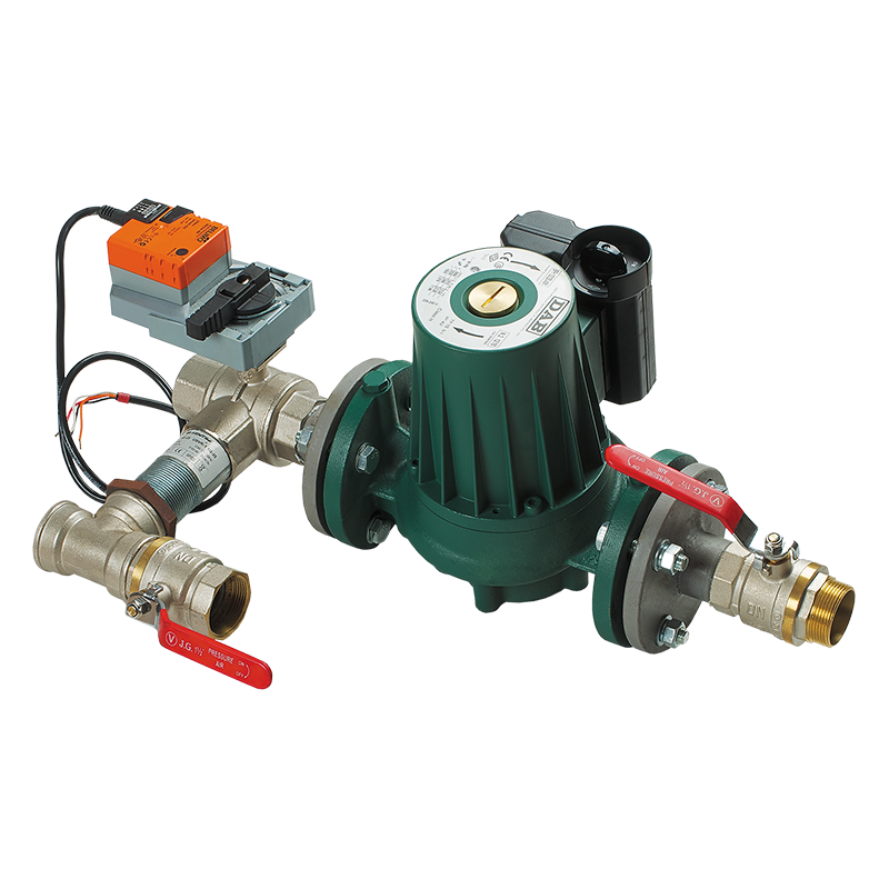
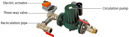
DESIGN
The water mixing unit consists a circulation pump, a three-way electrically actuated heat medium control valve and a recirculation pipe. The three-way valve is designed for smooth mixing of the heat medium stream from the heating (cooling) system and the return heat medium in a required proportion to regulate the heat medium temperature supplied to the water heating or cooling coils. The three-way way is actuated with a control 0–10 V signal from the ventilation control system. The mixing unit is rated for heat medium operating pressure in the mixing set 10 bar.
|
| Parameter | WMG 1 1/2-25 | Measurement unit |
|---|---|---|
| Circulation pump | DAB BPH 120/250.40M | - |
| Three-way valve control way | 0…10 V | - |
| Electrically actuated three-way valve | R339G | - |
| Three-way valve actuator Belimo | SR24A-SR | - |
| Connection type | Flanged connection | - |
| Three-way valve nominal diameter | DN 40 | - |
| Three-way valve heat medium transmission factor (Kvs) | 25 | - |
| Max. mixing unit flow capacity | 14.0 | m³/h |
| Developed head | 110000 | Pa |
| Connected spigot diameter | 1 1/2" | - |
| Transported heat medium temperature | -10...+120 | °С |
| Max. glycol content in the transported heat medium | 30 | % |
| Number of pump speeds | 3 | - |
| Phase / Pump supply voltage / 50 Hz | 1 ~ 230 | V |
| Max. pump power | 510 | W |
| Weight | 23.0 | kg |
| Series | Connected spigot diameter [in] | Heat medium transmission factor (Kvs) | |
| WMG | 3/4; 1; 1 1/4; 1 1/2; 2 | – | 4; 6; 10; 16; 25; 40 |
RECOMMENDED CONNECTION TO WATER NETWORK
| T1 and T2: heat medium supply and return pipeline P1 and P2: water pressure gauges for supply and return pipes 1: mixing unit 2: water heater 3: electrically actuated three-way valve 4: circulation pump 5: shut-off valve 6: supply and return pipes from the heat distribution system to the water heater 7: non-return valve 8: balancing valve 9: coarse filter | 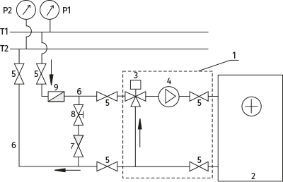 |
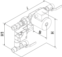
| Model | Dimensions [mm] | |||
| B | H | H1 | L | |
| WMG 1 1/2-25 | 266 | 420 | 255 | 610 |
| Mixing unit selection: find the required heat medium flow through the heating (cooling) unit as well as heat medium pressure drop (available head). These parameters are determined using the heating or cooling unit calculation diagram for each water heating or cooling unit. | 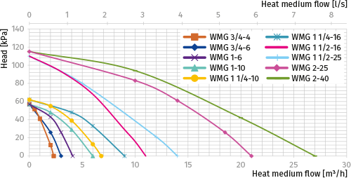 |