Login
Not registered yet? Take advantages of registration:
Products saving in a binding to the projects
Online consultation from experts
Signup

Privacy policy

Blauberg BLAUBOX MW 1800-4 Pro


Supply ventilation unit. Maximum air flow up to 1870 m³/h.
EAN codeEAN4058448037337
  • Description
  • Characteristics
  • Downloads
  • Designation key
  • Accessories
  • Overall dimensions
  • Additional diagrams
Description
Description
FEATURES

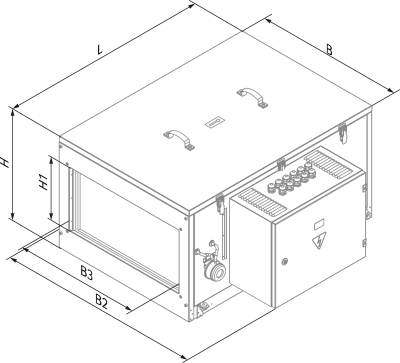
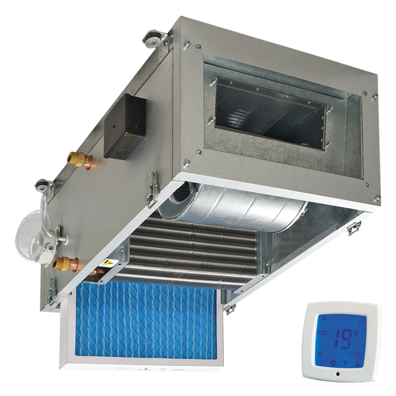
Ventilation units for efficient supply ventilation in various premises.Controllable air supply, heating and filtration.Compatible with 400x200 up to 800x500 mm rectangular air ducts.

DESIGN

The casing is made of double-skinned aluzinc panels, internally filled with 25 mm mineral wool layer for heat and sound insulation.The casing has fixing brackets with vibration absorbing connectors for easy installation.The hinged casing side panel ensures easy access to the internals for cleaning, filter replacement and other maintenance operations.


FANS

Asynchronous external rotor motor and centrifugal double-intake impeller with forward curved blades is used for air supply.Single- or three-phase motor modification depending on the fan model type.Integrated motor overheating protection with automatic restart.Dynamically balanced impeller.Equipped with ball bearings for longer service life.Reliable and quiet operation.
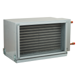
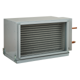
AIR HEATER

The units are equipped with a water (glycol) heater for operation during cold seasons at low outside temperature.The air temperature sensor downstream of the water heater and the return heat medium sensor ensure freezing protection of the water heater. If any of these sensors detects a temperature point below the set minimum value, the signal is sent automatically to the control unit to troubleshoot cooling.

AIR FILTRATION

The built-in G4 supply filter provides air filtration.

MOUNTING

The unit is suitable for mounting on the floor, ceiling mounting or wall mounting with fixing brackets in any mounting position except for the vertical one with air flow downwards.The correct mounted unit must provide free access to the hinged panel for servicing and filter replacement.

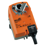
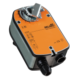
  CONTROL AND AUTOMATION

The units incorporate an integrated control system with a wall-mounted control panel and LCD display.The standard delivery set includes a 10 m cable for connection of the unit and the control panel.Control panel functions:

  • Activating/deactivating the unit.
  • Setting low, medium and high speeds for the supply fan. Air flow control.
  • The models with a water mixing unit have the function of setting and maintaining the supply air temperature by means of controlling the heat medium control valve.
Automation functions:
  • Supply air temperature control by means of controlling the heat medium control valve.
  • Control of the supply air damper actuator (separate order).
  • Control of the external circulation pump on the heat medium feed line.
  • Regulation of heat medium flow in the water heater in case of the differential pressure of the return heat medium below 40 kPa.
  • Water heater freezing protection with the mixing unit and the circulation pump.
  • Control of the cooler with respect to the set indoor air temperature (separate order).
  • Supply fan control.
  • Supply filter clogging control.
  • Shutdown of the unit on signal from the fire alarm panel.
Characteristics
Characteristics
Parameter BLAUBOX MW 1800-4 Pro Measurement unit
Number of water coil rows 4 -
Connected air duct size 500х250 mm
Voltage 230 V
Phase 1 ˜
Frequency 50 Hz
Current 2.15 A
RPM 1100 min-1
Maximum air flow 1870 m³/h
Maximum air flow 519 l/s
Total unit power 490 W
Sound pressure level at 3 m 40 dBА
Transported air temperature -25...+40 °С
Insulation 25 mm mineral wool mm
Supply filter G4 -
EC motor no -
Weight 62.5 kg
Casing material aluzinc -
Outdoor mounting no -
Sound-insulated casing yes -
Air duct for rectangular air ducts -
Design centrifugal -
Type Supply -
Mounting ceiling mounting, wall mounting, floor mounting -
ErP 2016, 2018 -
Documents archieve
Documents archieve
Select a document type
  • Catalogues
  • Technical documentation
  • Certificates
Name
BLAUBOX MW Pro - data sheet (pdf 942.04Kb)
BLAUBOX MW Pro - image (png 725.62Kb)
Control system for units based on Freemax controllers and AC208A2 sensor control panels - user’s manual (pdf 6.61Mb)
Designation key
Designation key
Series Casing modification Heater type Rated air flow [m³/h]   Number of water coil rows Control
BLAUBOX M: single-block unit W: water heater 750; 1200; 1800; 2100; 3000; 3200; 6500 4 Pro: with control panel
Accessories
Accessories
    BLAUBOX MW 1800-4 Pro
G4 panel filter FP 545x390x47 G4
Silencer SD 50x25
Duct cooling unit KFK 50x25-3
Duct cooling unit KWK 50x25-3
Water mixing unit WMG
Air flow dampers SL 50x25
Flexible anti-vibration connector EVA 50x25
Air damper electric actuator LF230
Air damper electric actuator TF230
Overall dimensions
Overall dimensions

Model Overall dimensions [mm]
B3 B B2 H1 H L
BLAUBOX MW 1800-4 Pro 500 600 775 250 480 800
Additional diagrams
Additional diagrams

HOW TO USE WATER HEATER DIAGRAMS
The air flow is 1500 m³/h and the air speed in the cooling unit is 3.5 m/s ➀.To calculate the maximum air temperature find the intersection point of the air flow line ➀ with the rated outer temperature shown in blue line (e.g., -25 °C) and draw the line ➁ to the left until it crosses the water in/out temperature curve (e.g. +70/+50). From this point draw a vertical line to the supply air temperature downstream of the heater (+30 °C) ➂.To calculate the heater power find the intersection point of the air flow ➀ with the rated winter temperature shown in red line (e.g., -25 °C) and draw the line ➃ to the right until it crosses the water in/out temperature curve (e.g. +70/+50). From this point draw a vertical line to the heater power axis (33.0 kW) ➄.
To calculate the required water flow in the heater prolong this line ➅ downwards to the water flow axis (0.42 l/s).To calculate the water pressure drop in the heater find the intersection point of the line ➅ with the pressure loss curve and prolong the line ➆ to the right on the water pressure drop axis (10.0 kPa).

AccessoriesSimilar products