Domestic fans
 Industrial fans
 Single-room air handling units with heat recovery
 Air handling units
  Smoke extraction and ventilation
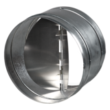
 Ventilation accessories
 Ventilation ducts and fittings
 Air distribution
 Measurement and control technology
 Ventilation sets and vents
Blauberg KOMFORT EC DW 2000-2 R

 EAN4058448021459
 - Description
- Characteristics
- Downloads
- Designation key
- Accessories
- Dimensions
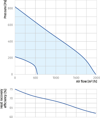
- Capacity diagram
| FEATURES
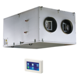
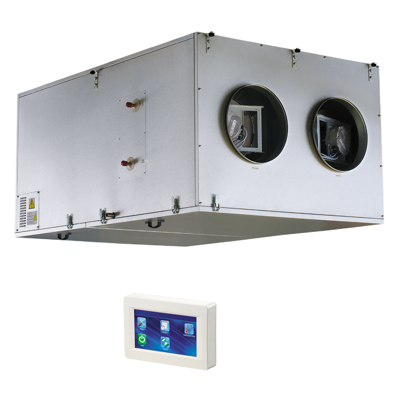
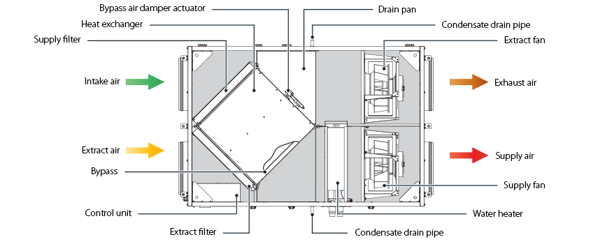
Air handling units for efficient supply and exhaust ventilation in flats, houses, cottages and other buildings. Heat recovery minimises ventilation heat losses. Provide controllable air exchange to create the best suitable indoor microclimate. Compatible with round Ø 200 to 400 mm round air ducts. DESIGNThe casing is made of double-skinned aluzinc panels, internally filled with 20 or 25 mm mineral wool layer for heat and sound insulation. The casing has fixing brackets with vibration absorbing connectors for easy installation. The spigots for connection to the air ducts are located at the side of the unit and are rubber sealed for airtight connection to the air ducts. The service panel ensures easy access to the internals for cleaning, filter replacement and other maintenance operations. |
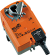
High-efficient external rotor EC motors and centrifugal impellers with backward curved blades are used for air supply and exhaust. EC motors have the best power consumption to air flow ratio and meet the latest demands concerning energy saving and high-efficient ventilation. EC motors are featured with high performance, low noise level and totally controllable speed range. Dynamically balanced impellers. |
|
|
|
||
| HEAT RECOVERY
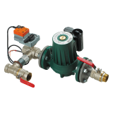
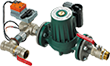
The unit is equipped with a plate counter-flow aluminium heat exchanger for heat recovery. The unit condensate is collected and drained to the drain pan under the heat exchanger. The air flows are completely separated in the heat exchanger. Thus smells and contaminants are not transferred from the extract air to the supply air. Heat recovery is based on heat and/or humidity transfer through the heat exchanger plates. In the cold season supply air is heated in the heat exchanger by transferring the heat energy of warm and humid extract air to the cold fresh air. Heat recovery minimizes ventilation heat losses and heating costs respectively. In the warm season the heat exchanger performs reverse and intake air is cooled in the heat exchanger by the cool extract air. That reduces operation load on air conditioners and saves electricity. FREEZE PROTECTIONThe electronic frost protection system based on bypass and heater is used to prevent the heat exchanger freezing in cold seasons. The bypass damper is opened and the heater is turned on automatically according to the feedback from the temperature sensor. Cold intake air passes by the heat exchanger and is warmed up to set temperature in the heat exchanger. Synchronously extract air that passes by the heat exchanger is used for its defrosting. After a freezing danger is over the bypass damper is closed, the heater is turned off. The unit reverts to the normal operation mode. AIR HEATERThe unit is equipped with a water (glycol) heater for operation at low outside air temperature. The integrated water heater is activated to warm up supply air flow if set indoor air temperature may not be reached by means of heat recovery only. Heat medium temperature control ensures supply air temperature maintaining. The air temperature sensor downstream of the waterheating coils and the return water temperature sensor are used for freezing protection of the water heater. |
AIR FILTRATION
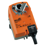
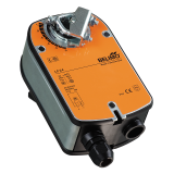
The built-in G4 supply filter and G4 extract filter provide air filtration. CONTROL AND AUTOMATION
Mounting to the ceiling with fixing brackets. The correct mounted unit must provide free condensate collection and drainage as well as good access for servicing and filter replacement. Servicing access on the bottom. |
|

| Parameter | KOMFORT EC DW 2000-2 R | Measurement unit |
|---|---|---|
| Voltage | 230 | V |
| Phase | 1 | ˜ |
| Frequency | 50/60 | Hz |
| Current | 5.00 | A |
| Power | 840 | W |
| RPM | 2920 | min-1 |
| Maximum air flow | 1950 | m³/h |
| Maximum air flow | 542 | l/s |
| Number of water coil rows | 2 | - |
| Sound pressure level at 3 m | 58 | dBА |
| Insulation | 25 mm mineral wool | mm |
| Transported air temperature | -25…+40 | °С |
| Extract filter | G4 | - |
| Supply filter | G4 | - |
| Heat recovery efficiency | 75 | % |
| EC motor | yes | - |
| Heat exchanger type | cross-flow | - |
| Heat exchanger material | aluminum | - |
| Weight | 194 | kg |
| Connected air duct diameter | 315 | mm |
| Casing material | aluzinc | - |
| SEC class | NRVU | - |
| Mounting | ceiling mounting | - |
| ErP | 2016 | - |
| Series | Motor type | Mounting type | Heater type | Rated air flow [m³/h] | Number of water coil rows | Service side | |
| KOMFORT | EC: electronically commutated motor | D: suspended mounting, horizontally directed spigots | W: water heater | 2000; 3800 | – | 2 | R: right |
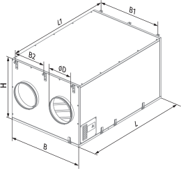
| Model | Overall dimensions [mm] | ||||||
| D | B | B1 | B2 | H | L | L1 | |
| KOMFORT EC DW 2000-2 | 314 | 950 | 915 | 405 | 761 | 1400 | 1453 |